Mike Lockwood's Foucault Testing Hall of Shame
Well, after lots of mirror testing I have seen some mirrors that just
stood
out in terms of the problems they showed on the test stand. The
most
interesting of the worst of them are shown here, in no particular
order,
and sparing no optician. The first two mirrors' images were taken
by me with my
digital
camera through my small 3x finderscope that is used on my slitless
Foucault
tester with a blue LED light source. The scope consists of a
~30mm achromatic lens with ~80mm focal length. Eypiece in the
scope is a 26mm (~3X), which gives nice sharp images. It is
refocused for mirrors at different distances from the tester.
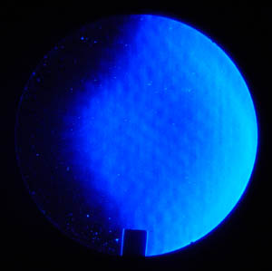
Mirror 1:
Here are some images of a 6" F/8 mirror (coated).
It
was in a telescope that was donated to our local club. It has the
absolute
worst case of turned-down-edge (TDE) that I have ever seen. The
outer
1/8"-3/16" of the mirror had a radius of curvature more than two inches
longer
than the rest of the mirror!
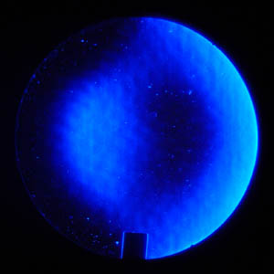
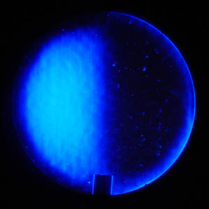
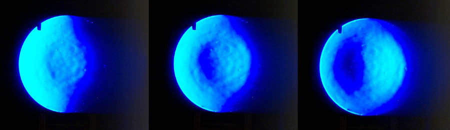
Mirror 2:
This is a 10" F/6.8 mirror (coated), also from a
donated
telescope. It has a very unique form of surface roughness, a very
regular
pattern that resembles chicken skin, a golf ball, or puffy patches of
clouds,
depending on how you look at it. The way I look at it, it is just
plain
bad, the mirror has over three times the correction it should have, a
mild
turned edge, and there are hints of astigmatism in the third image.
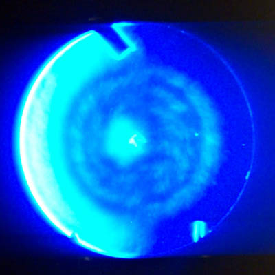
Mirror 3:
This is another 6" F/8 mirror (coated), made recently
by Coulter Optical.
As you can see, it resembles a bullseye more than a parabola, but
it
did actually meet the specification of being a 1/8-wave mirror on the
surface! This
is machine work gone wrong, with zones carved in due to a repeating
pattern. Image was taken with a friend's (John Stone) digital
camera positioned directly behind the knife edge.
Mirror 4: This was a 12" F/6 mirror from Cave (from the
seventies,
I believe). The figure was not that bad, but the surface
roughness
made me decide to refigure it. It is now and excellent
performer. Image also taken with a camera directly behind the
knife edge.
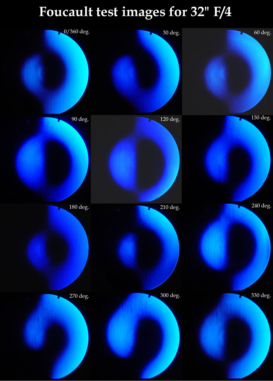
Mirror 5:
Here is arguably the worst of all. Below you can see a composite
of 12 images taken of a 32" F/4 mirror. (I can't say anything
about the source of the mirror so don't ask.)
The mirror was rotated 30 degrees between photos. Astigmatism can
be seen in most images, and its form changes systematically with the
rotation of mirror. A layer of carpet supported the bottom of the
mirror on a curved support. There is some central zoning, too,
and other problems that I won't mention.
The main point is this
is what astigmatism looks like with the Foucault test. In some
orientations, it is not so obvious (120 deg.), but rotate the mirror a
little bit and there it is. Pure astigmatism goes from invisible
to most visible in only 45 degrees of rotation, so be thorough and
careful. The moral is, rotate the mirror on the test stand
and see if the shadows change.
By the way, we could not measure the difference of correction in a
statistically significant manner for this mirror. That is, the
corrections were different within certain zones for the two diameters,
90 degrees apart, which were our best estimate of the major and minor
axes. However, there was not an obvious difference in overall
correction - it merely indicated some local zoning in the neighborhood
of 1/8th wave. However, this mirror clearly has astigmatism in
the amount of many of waves. (If anyone cares to estimate it, please do and send a note
to the ATM list!!)
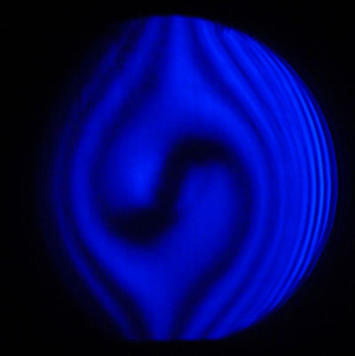
To top it all off, a ronchi photo is shown below. Given the
Foucault images, it is easy to guess what it would look like - an S in
the middle of the mirror. (It's a bird, it's a plane - no it's
SUPERastigmatism!)
No, I don't know the distance from COC of the photo. Grating was
probably 133 lines per inch.
Hall of Fame
Well, I had intended to put this up sooner, but taking images that
accurately depict what your eye sees when doing the Foucault test is
not easy. The images below are my best so far, but there is still
much room for improvement. The vertical bands which may appear to
be surface roughness are NOT on the mirror, and their position moves as
the small scope (which I use on my Foucault tester) is rotated.
My digital camera is positioned at the eyepiece and records the images
through the scope. Visually, the mirrors look exceptionally
smooth.
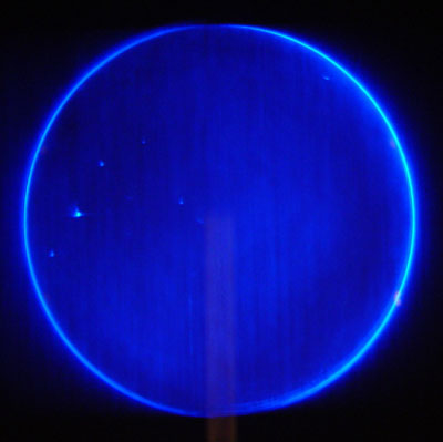
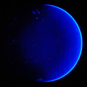
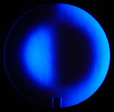
First mirror is my 10" F/12.5
reference sphere, pictured at right. The mirror was
uncoated when this images was taken. Images in this section were
taken with my digital camera and 3X scope behind the knife edge.
The back of the mirror was fine ground, so no spurious reflections can
foul up the photos.
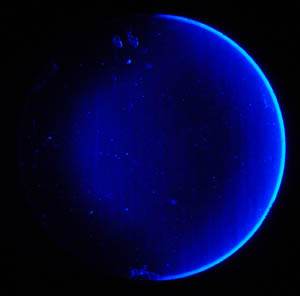
The pattern vertical "lines" or
texture is NOT ON THE MIRROR SURFACE - it is due to something in
the small 3x scope that my digital camera takes images with, and seems
to be caused by small amounts of dirt on the eyepiece of this small
scope. The vertical pattern
MOVES WITH THE ROTATING EYEPIECE, proving it is an artifact of the
imaging, not the mirror. To the eye, the surface is REALLY smooth, and the difference in
gray level is MUCH less apparent than it is in the photo.
The small brighter spots are light reflection off defects in the glass
(bubbles, etc.) which are well below the surface. Note the bright
diffraction ring all around the mirror.
At the right a slight darkening can be seen an inch or two inside the
edge. (Again, to the eye this difference in brightness is not
nearly as apparent.) This is a slight error where the surface turns
upward slightly for ~1.5", and it has a slightly shorter ROC than the
other portions of the mirror. The difference in null positions
between the null for it and the nulls of the outer zone and the central
area of the mirror is 0.005" for my moving source tester, which
corresponds to a wavefront error of ~1/100th wave on the wavefront,
according to FigureXP.
The darkening at the upper left, especially near the 10 o'clock
position is due to an AIR CURRENT. It is very difficult to get
air still enough to record an uncorrupted image of a mirror that
approaches a 1/100th wave (wavefront error) sphere!
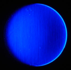
The next mirror, pictured at left, is of my (coated) 13.1"
mirror. It is Pyrex, 7/8" thick at the edge, and is gently
supported at the bottom edge by a conforming curved block lined with
pile-type weatherstripping. Again, the back is fine ground.
As above, the vertical texture is due
to something in the imaging train, and is not present on the surface.
This mirror is exceptionally smooth to the eye. Again, note the
diffraction ring at the left (some of it was lost when I resized the
image).
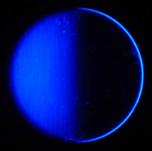
It was interesting to watch the air
currents move, particularly in the nulled area where the darker
regions join at approximately the 60% zone directly above the center of
the mirror. Many photos were taken to try to get an image with
quiet air, and this is the best, though it is not perfect. The air currents slightly darken the region
mentioned before, which to the eye matches the region of the 60% zone
below the center.
There are also traces of air currents (more visible on other photos)
just below the center of the image, in the form of a slight
bulge. If viewed at the wrong moment, the air currents can give
the impression of slight astigmatism by making the light-dark
transition region (running vertically along the center of the mirror)
tilt slightly, as it does in this image. In reality, though, the
transition is perfectly straight, which is not indicative of
astigmatism. It should be noted that in this image, the knife
edge was not perfectly vertical, and makes the transition line appear
to tilt slightly to the left at the top of the image. This makes
no difference at all.
In reality, this mirror is beautiful to the eye when viewed on the test
stand, and it is typical of what my
parabolic mirrors look like when I am finished with them - there are no
visible zones, surface texture, or hints of astigmatism.
If any of you on the ATM list can give me some insight into the cause
of the vertical artifacts, please post a message.