Spherometers
by Mike Lockwood
These notes are based on my actual use of spherometers. I find
spherometers more convenient and often more accurate than the
sun test, flashlight test, etc., done on a wet, oiled, or soapy
mirror.
The size of a spherometer depends on the application. If you just
want to measure sagitta at the center of a mirror or flat, then you
want a spherometer base that's nearly as big as the mirror, so long as
you can make a base that doesn't flex appreciably. However, using
a base that is smaller than the mirror allows it to be moved around,
and you can detect local high and low spots such as zones that are
produced during fine grinding (and which may take significant time to
polish out).
Calibration
It is important to realize that you need a "standard" to calibrate the
spherometer on, and it must be at least as large as the base you wish
to calibrate. This standard is a decent
flat (1/2 wave to 1/4 wave is fine), or a mirror of known radius of curvature.
The spherometer is typically zeroed while on the standard, and all
readings are taken with reference to that calibration point.
I have a few different spherometer bases from 2" to 6" diameter,
meaning the radius of the three feet from the center is 1" to 3".
I use the 6" the most, and I may make an even larger base in the
future.
All bases are aluminum disks (except for one made from a pulley) with
three ball-bearing
feet.
That covers my needs of measuring all or portions of mirrors of nearly
all sizes. All bases have glued-in
ball bearings
as feet, and I
used a good pair of calipers to measure their separations. This
was used in the spherometer equations to develop more accurate tables
of ROC as a function of measured sagitta for a chosen base.
However, a better calibration method
is to solve for the effective radius of the spherometer feet by
measuring the sagitta of a mirror for which the radius of curvature is
known to an accuracy of 1/8" or less. Measuring more than
one mirror of known ROC will help you judge the ultimate accuracy of
the spherometer. Sagitta measurements can be done with uncoated
mirrors or coated mirrors, so long as you are careful not to slide the
spherometer base around. Paraboloids of normal focal ratios (F/4
and slower) should work fine for calibration - the asphericity will not
affect the measurements too much, but if you have any doubts, calculate
the asphericity for the parabola you are using, especially if it's
fast, and take it into account.
After you have calculated the effective radius of the spherometer feet
from the center, you can simply plug it into the equation and calculate
the ROC for various spherometer readings. I wrote a computer
script to calculate a table
of ROCs for each base that I calibrate, for both concave and
convex
surfaces. Note that the
formulas for the sagitta are different for convex and concave surfaces
assumign you use balls for the feet of the spherometer base!
I often measure mirrors from optical systems that I
have no information about, so these tables save much time and possibly
some calculation errors. At minimum, carefully calculate the
ideal spherometer reading for the radius of curvature you are trying to
hit.
Usage
Repeatability of the readings increases as your mirror becomes more
spherical - that is, as your grit size decreases. There
are two reasons for this. Many don't
realize that a mirror is not a fairly good sphere until fine
grinding. You can easily convince yourself of this by using a
spherometer with an indicator that reads to 0.00005". Also, large
pits will throw off the readings as you slide the spherometer around on
the surface. So, sliding the base (carefully) across the mirror
from one side
to the other, you can see significant changes in the sagitta that you
measure due to both asphericity and a rough surface.
Don't worry about waiting for the glass to equilibrate unless it just
came out of the freezer. Unless it is large, thin, plate glass
blank with strain, I doubt you will ever measure an effect of glass
changing shape due to heat by using a spherometer. I haven't ever
seen it with Pyrex.
Flexure and thermal expansion of the base can be
problems. To avoid
flexure, use metal at least
3/16" thick, and thicker for diameters over
4". I like aluminum -
this helps
avoid making the base heavy, which will help
avoid scratches. To avoid thermal expansion issues with the base
itself, don't handle the spherometer any more than necessary. If
you
are zeroing it on a flat (or other reference surface) keep them side by
side, so you can move the spherometer from one to the other with a
minimum of handling.
Make sure any glass surfaces and the feet of the base and the tip of
the dial indicator are clean
before measuring. A quick wipe with a fingertip does the trick.
Following these suggestions, I get repeatability down the the accuracy
of my best indicator (0.00005") with my
spherometer bases. That's a little over two waves over the
diameter of the spherometer base.
Accuracy
I calibrate my spherometer bases on mirrors of know radius of
curvature. Using this calibration method on my largest
spherometer base, and with the repeatability mentioned above, for mirrors of around 60"-80" focal length
I can easily control radii to +-0.25" fairly easily, and thus focal
length to within 1/8".
I find spherometers very useful for making flats, too - one can get the
surface flat to a handful of waves before polishing. It is also
indispensible for precise control of radii, especially for
Cassegrain secondary mirrors with high magnification factors, where
slight differences can change the system focal length by inches.
Seems like an ideal instrument for controlling the curves on refractor
lens elements, too.
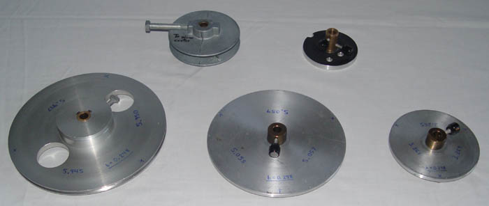
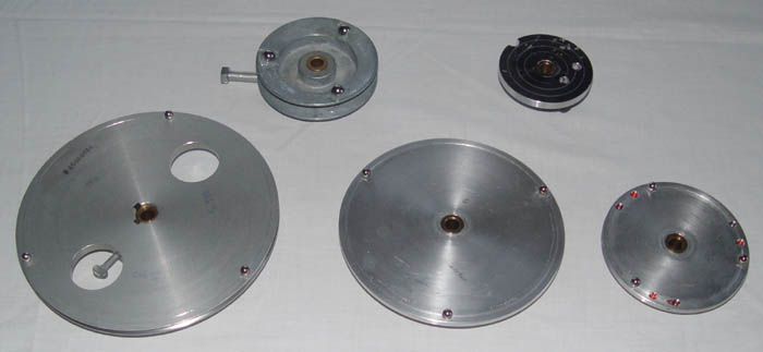
The spherometer bases I use are shown below, first the top, then the
bottom,
the latter showing the bearing placement.
Sizes range from 2" to 6" diameter of the circle that the bearings are
layed
out in. The ball bearing feet on the pulley are 3/8" diameter and
are
epoxied on. The other disks have 1/4" bearings that are super
glued
on. All bases are made of aluminum. All have bushings of
bronze-type
material to hold the dial indicator. The right-most three bases
were
pieces of aluminum plate turned in a lathe.
Holes for the bearings were drilled with a countersink bit. A
circle
was scribed in while the disks were still mounted in the lathe, to aid
in
hole location for the bearings. Dividers were then used to evenly
space
the holes around the circle so that the bearings would be as close to
the
same distance apart as we could get them.
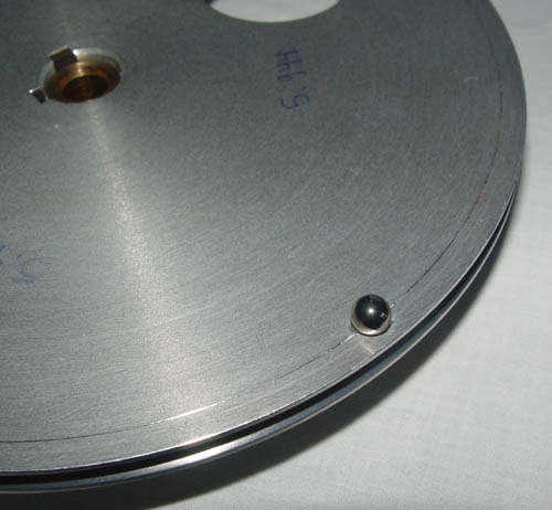
A closeup of one of the bearings and the scribed circle on the large
disk
at bottom left, is shown below. This disk was a pulley bought at
a
surplus store for ~$7. The distance between two of the bearings
is
written on the bottom of the disk, and can be seen in the top middle of
the
photo.
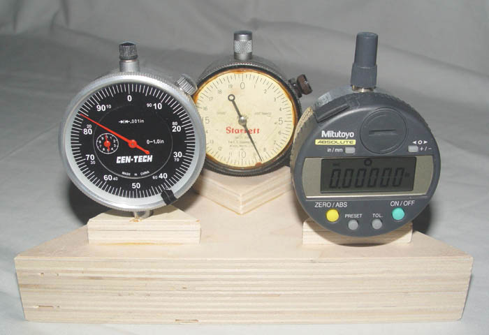
Finally, the three indicators that I commonly use are shown below,
sitting
in a holder that I made from scrap plywood. The holder ensures
that
the plunger is not depressed while the indicators are in storage.
The
indicator at left is a ~$10 model, suitable for rough measurement and
use
on a Foucault tester. The one in the back reads to 0.00025".
The
one on the right gets the most use, and will read to 0.00005" quite
accurately
and repeatably. How many waves is that? How many microns?
See
my mirror-making conversion chart to get
an
idea.