10" F/8.75 truss-tube Dobsonian
A while back I traded some refiguring work for a couple of 10" mirrors,
both
of which were figured, but not polished out! I spent quite a few
hours
polishing and figuring both an F/5.5 and an F/8.75 mirror, and then
when
they were finished they proptly were wrapped up, placed in a container
and banished
to
a closet while I finished up other projects (like a 12.5" Cassegrain, a
16.25"
Cass., and many other refigures). This summer I decided I would
finish
this long-focus dob in time for Mars, and I set a self-imposed deadline
of
Sept. 7th, the day before the start of Astrofest 2005 (for a report, click
here).
Well, starting at the beginning of August I got to work. I
decided
to build the major parts of both the F/5.5 and the F/8.75 scopes at the
same
time, thereby saving time. I made the mirror box, mirror cell,
and
diagonal cage for both scopes early in the month. First light for
the
F/8.75 was achieved on Sept. 6th when I viewed some brighter stars in
the
northern sky from my driveway. Through haze, the star test looked
excellent,
and the focal plane was found to be at a spot where all my eyepieces
could
come to focus. For once I didn't have to trim the truss poles!
Anyway, Astrofest 2005 was good for planetary viewing, and I enjoyed
some
excellent views of Mars in the early morning hours. Those views
made
all the work of the scope worthwhile, and I now have a great
appreciation
of the images that can be deliverd by such a long-focus Newtonian.
The
scope has excellent contrast on deep-sky objects, even with the truss
tube construction and no shroud. The cage is fairly well baffled,
and will be even better soon.
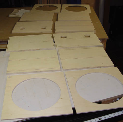
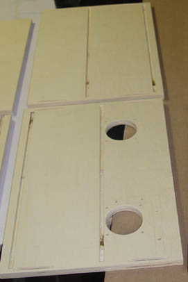
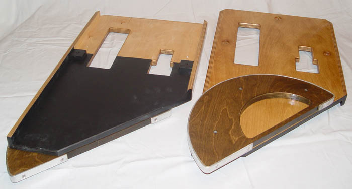
Construction
The mirror box for the scopes consisted of 1/2" Baltic Birch (BB)
plywood
sides, and two 1/4" BB baffles, one near the front of the box and one
nearer
the mirror. The parts for both boxes are shown below in the photo
at
left. The right photo shows the holes cut for ventilation fans in
the
top of the box and the dados (slots) cut to receive the baffles.
Biscuit
joinery was used to assemble the box sides, and no fasteners were
needed,
only glue.
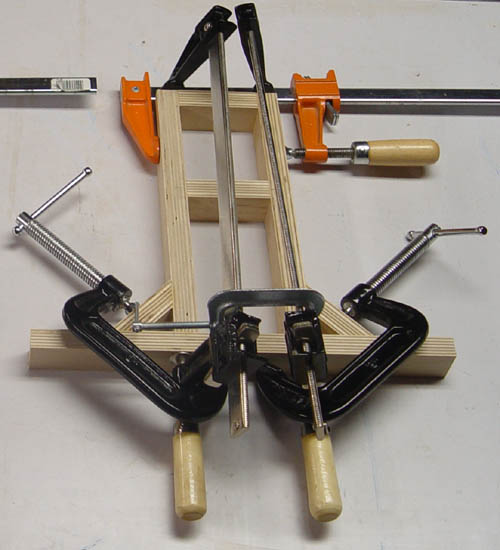
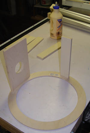
The box was assembled, and the mirror cells and diagonal cages were
also
put together. The cages and mirror cells were assembled with glue
only
first, and then reinforced with a single stainless screw into each
brace.
The rings of the cage are 1/4" BB, and the braces and focuser
board
are 1/2" BB. By the way, the glue, TiteBond II, has water cleanup
and
is stronger than the wood when properly used. You don't need to
use
Gorilla Glue to get high strength. (If you try to pull a joint
apart,
you will pull a layer of the plywood off!)
After adding various other parts, the mirror boxes and cages were
stained
and painted. The fans were installed in the box and wired up.
A
plastic cover was added to the back of the mirror cell, to block stray
light
and allow air to only enter from the bottom, encouraging air flow up
and
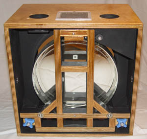
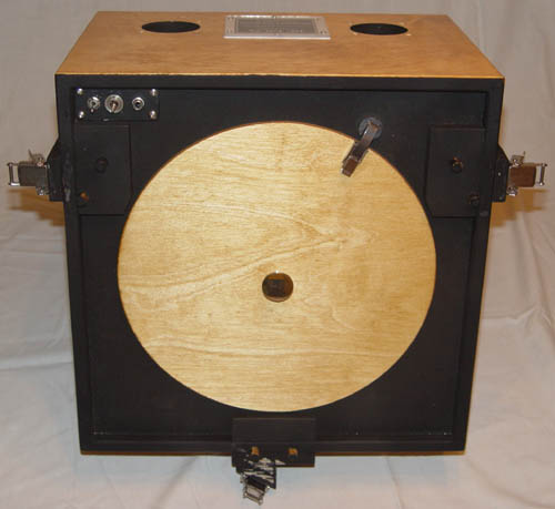
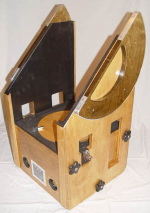
around the mirror. Below is a photo of the front of the mirror
box
with the mirror cover off, and the back of the mirror with the back
cover
removed and installed.
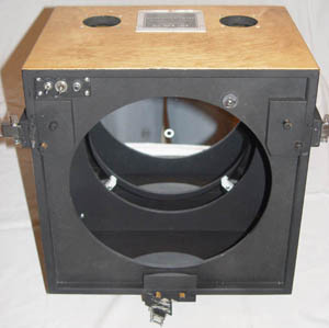
Here's a large photo of the mirror cell without mirror, showing the
ball swivel and the two adjustmend bolts and their associated springs,
etc.
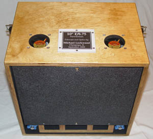
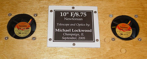
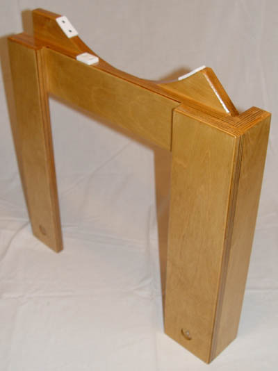
Here is a photo of the front of the box with the cover on. Note
the
dowels and latches that locate the truss poles. The second photo
is
a view of the name plate that I made for the scope from a transparency
printout
sandwiched between a piece of white plastic and a piece of plexiglass.
Yes,
I made it.
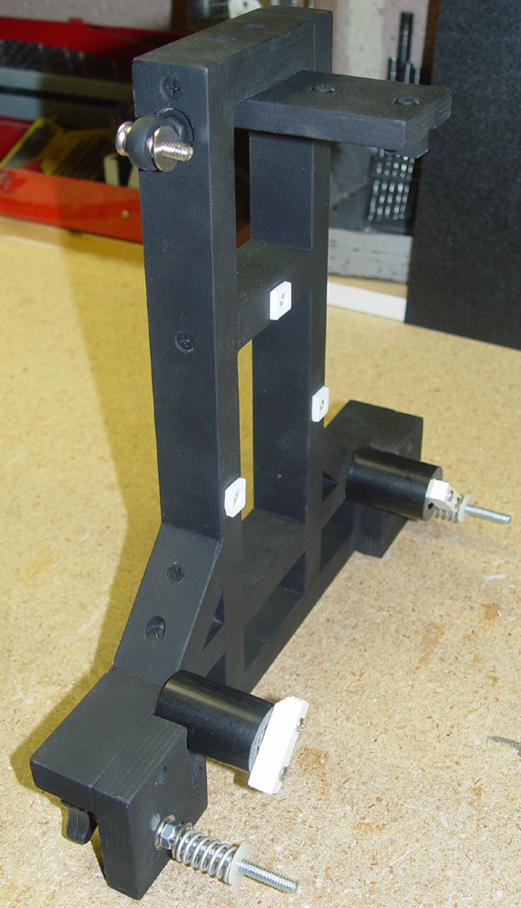
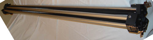
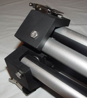
Next, the 6-pole truss assembly was made. This assembly collapses
like
a folding camp chair into a compact clump of poles. When
expanded,
holes or dowels (depending on which end you look at) locate the wooden
"hinges"
, to which the poles are attached, on both the rocker and diagonal
cage.
Then six stainless, spring-loaded latches are snapped and the
scope
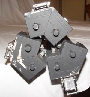
is assembled. Here are photos of the poles and closeups of the
"hinges".
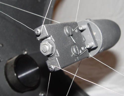
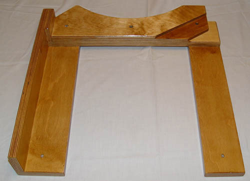
The hinges are made of mainly 1/2" BB. First, a long length of
"U"
channel is made from the BB, and then pieces are cut, with one end of
each
piece cut at a 30 angle. When two pieces are glued together, this
forms
the 60 angle that is required for the poles to fold up. This
angle
can be see in the left photo in the second row below. The dowel
pins
are also visible, and these slip into holes in the secondary cage.
The cage is pictured below. Two of the attachment points for the
trusses and the attached "clips" for the latches are visible at the
bottom left and right of the cage. Focuser is a MoonLite single
speed crayford.
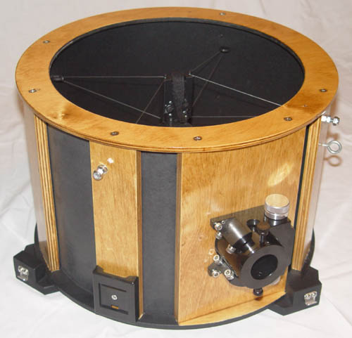
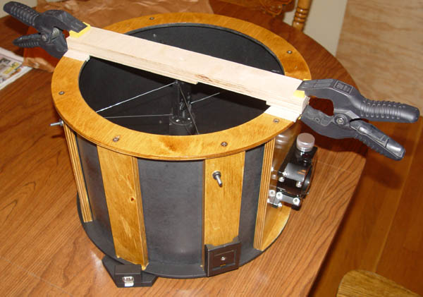
Yes, that's a wire spider. To string the spider, the central hub
was
bolted to a piece of plywood that was temporarily clampted to the top
of
the cage. Below is a photo of the central hub and the jig clamped
in
place.
With the scope able to be assembled, I put it together and made sure
the
truss poles were as close to the ideal length as possible, placing the
focal
plane about 1/4" above the top of the focuser when the focuser is fully
retracted.
Then I assembled the scope and balanced it with a 41mm Panoptic
in
the focuser. This gave me the highest possible balance point,
which
was something like 26" above the bottom of the rocker box. This
is
excellent for an F/8.75 scope. The "wings" were then made to
attach
the bearings to. The "wings" extend the sides of the 10" tall
rocker
box up to the balance point, and are removeable for easier transport.
The
wings are attached to the mirror box with plastic knobs with stainless
bolts
inserted and locked in place, forming handles with stainless threaded
shanks.
Below is a photo of the two wings with the bearings attached, one
turned
upside down. Note the black paint where it is exposed near the
optical
path. The next two photos are of the wings installed on the
mirror
box with three knobs apiece.
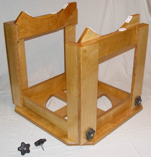
With the wings attached, the scope was re-balanced, and the balance
point
moved downward another 3"!! The wings were trimmed and the
bearings
moved down. Now the rocker box could be constructed, and I wanted
it
to come apart for easier handling. (My house is rapidly filling
with
telescopes, so I need things to break down and be compact!) The
base
of the rocker was made from 3/4" BB and four strips of 3/4" BB were
glued
and screwed in a square on top of it to reinfoce it. These strips
also
serve as attachment points for the rocker sides, and the T-nuts that
the
knobs screw into can be seen in the first photo. The rocker sides
were
glued together from ~4" strips of BB, and the curved sides were
attached
with screws. With only two knobs, the sides are still fairly
stiff.
However, later I will probably add a front brace/battery shelf to
stiffen
it up a bit. In any event, without a brace tracking at 450x is no
problem.
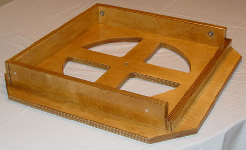
Below is a photo of the assembled rocker, with a couple of knobs
pictured
as well.
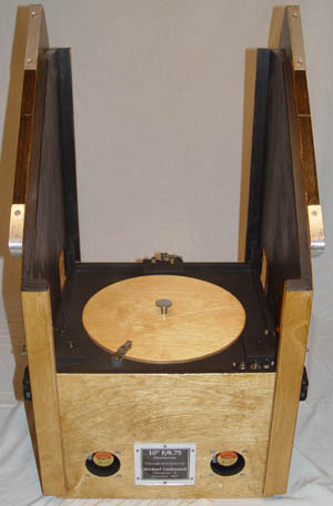
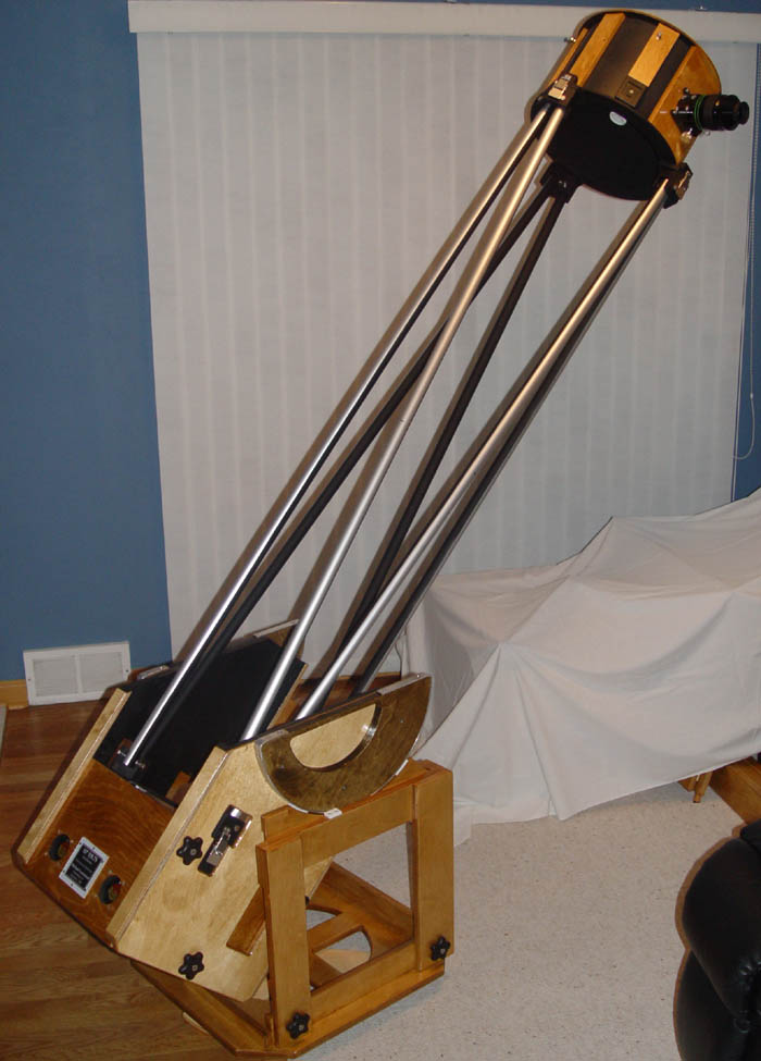
At last, it was time to assemble the scope. Here's a photo of it
set
up in my house. It is tall enough to require a good step-stool
(zenith
eyepiece height 7'+), but there is something strangely satisfying about
finally
having a scope that requires more than just a few inches for me to view
through
it. (My 16" F/4 requires about a 6" step when I point it at the
zenith
when it's sitting on my equatorial platform.) In the photo the
white
sheet is covering the 12.5" Cassegrain parts. Clearly I have too
many
scopes.
All parts (excluding bearings) are stained with Minwax "Golden Oak"
stain.
The bearings are a "dark walnut" stain by another company whose
name
eludes me. All wood parts are finished with two or three coats of
Minwax
fast-drying gloss polyurethane.
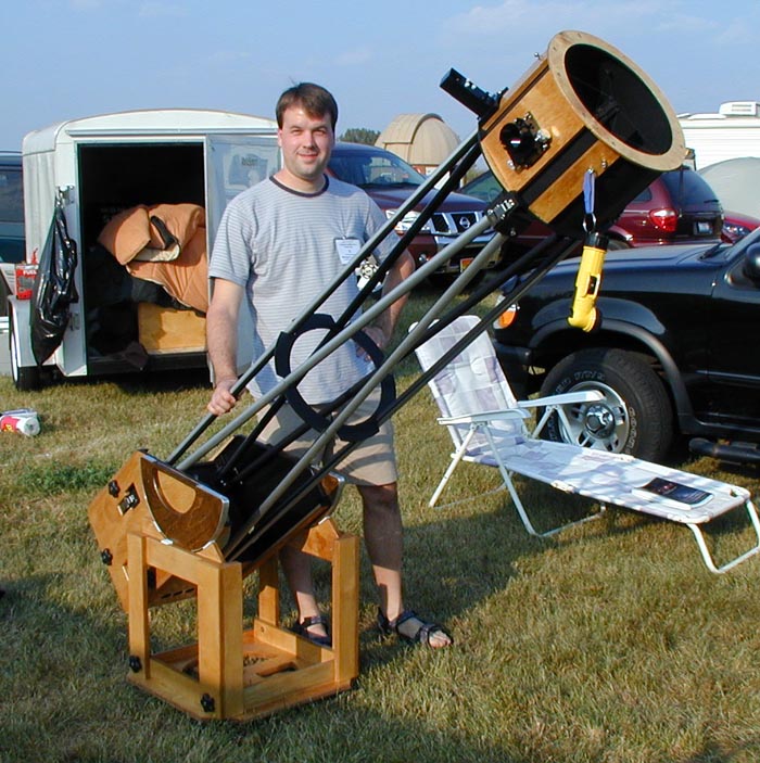
Here are a couple of photos (courtesy of Mike Conron) of the scope set
up at Astrofest
2005. The second photo shows the QuickFinder installed on the
secondary cage, the yellow flashlight counterweight that is attached
when light eyepieces are being used, and the central baffle/vibration
dampener. (The 30" F/3.8 is in the trailer behind the scope in
the photo.)

For my thoughts
on the scope, see my Astrofest
2005 report. What I will say here is
this - a friend and I compared his 12.5" F/5 Starmaster with
excellent
Zambuto mirror with my 10" scope while viewing Mars. Both scopes
had
equilibrated and were in good collimation. Comparing the view,
both
yielded excellent high-power images, but my scope had a bit more
contrast
and showed a bit more detail on the Martian surface.
Additionally,
the edge of the planet seemed a bit sharper to me. I attribute
these
differences mainly to the wire spider and smaller obstruction.
This telescope has altered my plans as to what to build next (besides
finishing
the 10" F/5.5). While I had planned to try an unobstructed
design,
I think I might shelve that project in lieu of making a larger moderate
focal-length
scope. By moderate I mean F/5. By bigger, I mean 20" or
22",
and still manageable by one person.