Building an open-tubed 12.5" F/12.5 Classical Cassegrain
By Michael E. Lockwood
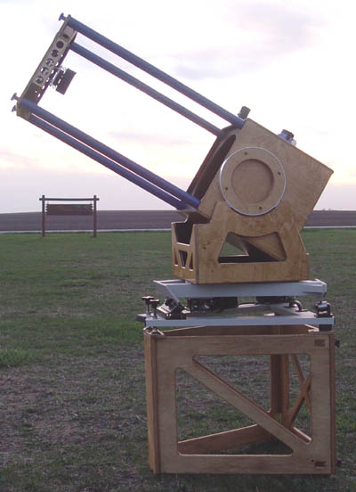
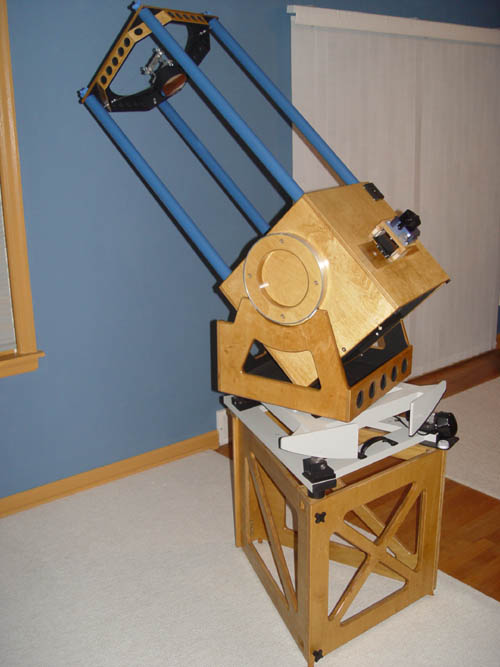
Figure 1: Telescope,
equatorial platform, and support platform,
waiting for darkness in the fields of Illinois.
Introduction
I've enjoyed watching the sky ever since I was a child, growing up in
the dark woods of northern Michigan. My father has always been a
builder of things (houses, hobby projects, etc.), and I am the same way
- I am always creating something. So, building telescopes
naturally grew out of my love of the sky. With some help, I built
three telescopes in high school, and used them quite a bit. After
finishing college and grad school and some house rennovations, in early
2002 I decided to finish a
mirror making project that I had started in 1989. With a little
advise, it came out quite well. My first
mirror, an 8" F/3.9, is something that I will never sell.
Fast forward three years - after making many Newtonian telescopes and
after grinding, polishing
and figuring about 20 parabolic primary mirrors (by hand), Mike Conron
and I made a 30" F/3.8 mirror with the aid of his grinding
machine. We did the final
figuring by hand. I had figured some very good fast mirrors
before, so I ended up taking charge of the figuring of this very big,
very fast mirror.
(Mike C. tended the machine through virtually all the grinding
and
polishing.) We put in a lot of time, and had a lot of fun (not to
mention
a few beers!), and when that mirror was done I was thrilled. (See
the end of the article for a link to my web site, which has a section
on the 30".)
But what could be the next challenging project after making such a big,
fast mirror?
My friend decided to thank me for the figuring help by giving me a
full-thickness, Pyrex, perforated 12.5" F/4.2 Cassegrain primary that
needed refiguring. That was the start of the project. Up to
that point, I'd only seen one amateur-made Cass, and one non-commercial
cass made by a professional optician, so I figured it must be a
challenging project to get both the
optics and the mechanics right.
I like a challenge.
Additionally, this type/size of long focus telescope can be used with
your feet firmly planted on the ground (no ladders), and often viewing
can
be done from a VERY comfortable seated position. More detail can
be
seen when you're comfortable. Putting the whole scope on a
tracking
platform would further increase viewing enjoyment, and would make
waiting
for that second of steady seeing much more bearable. The price
for
the convenience of the viewing position is that you must make a highly
precise convex mirror.
Cassegrains do have disadvantages - they can be difficult to baffle,
collimation requires a laser collimator and practice, there are more
optical surfaces to scatter light, and their mechanical construction is
not as easy as a Newtonian. I chose not to worry about the
disadvantages, and focus on the positive aspects of the design. I
wanted to use the scope and judge it for myself at that point, not
before.
After a lesson in the equations that define the design of a Cassegrain
telescope, I wrote a short, simple computer program to calculate
several designs with different focal ratios. Taking into account
the fact
that I wanted the focuser to sit on top of the mirror box, rather than
behind
the primary, I settled on a design with a focal ratio of F/12.5, about
as
fast as was practical given the primary's focal ratio (which I wasn't
about
to change!), a secondary of 4" in diameter, and a 32% obstruction
ratio.
The fully illuminated field has a diameter of 0.6". A 1.53"
elliptical
tertiary mirror, the same type as is used as a secondary mirror in a
Newtonian,
was located just in front of the primary mirror, and sent the light
path
out the top of the mirror box to the focuser. That is, instead of the light passing through the
hole in the primary mirror, it is reflected upward into a focuser
placed on top of the mirror box. This places the eyepiece
in the comfortable viewing position.
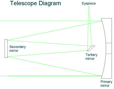
Figure 2: Telescope diagram
- green lines represent light path.
Primary mirror is concave, secondary mirror is convex, tertiary
mirror is flat. Not to scale.
Another advantage of the Cassegrain design is the long focal length -
high
magnification is possible with longer focal length eyepieces with more
eye
relief, and Jupiter's moons are disks, not the "comets" that they
become
in a fast Newtonian. (Many do not realize that the performance of
a perfectly collimated F/4.5 Newtonian will be limited by coma if an
object,
such as a planet, is not well-centered in the field of view.)
Magnifications
of upwards of 400x are achievable with a 9mm Nagler. On the other
hand,
A 41mm Panoptic provides 96x, which is low enough to make finding
objects
fairly easy, and viewing the entire moon possible. No vignetting
is
noticeable with this eyepiece, even with its enormous field stop!
So, here's a quick summary of why I did the project:
1) Challenge of fabricating a different
(non-Newtonian) optical system
2) Lack of amateur-made Cassegrains
3) Convenient viewing position
4) Compact telescope
5) Long focus - high magnification is easy, little coma
6) I already had a primary mirror blank that only needed
refiguring
My goals were
1) High optical quality, minimal spider diffraction
2) Ease of transport and assembly/disassembly, and
3) A unique telescope that might inspire others to make a Cassegrain.
At some point you might also wonder what tools I used. Most are
fairly standard woodworking tools. Here's a list of the power
tools:
10" tablesaw, 12" chop saw, router, jigsaw, drill,
drill press, orbital sander, biscuit jointer.
(I don't have a lathe or mill....... yet!)
Optical Fabrication
I'm an amateur optician,
working by hand. I use
the Foucault test
to test concave mirrors.
The tester was built in an
evening, and costs $20 or so, including a $10 dial indicator.
Nothing fancy here. It is pictured below. The "knife edge"
is actually a 1/16" x 1" piece of brass stock a few inches long.
The edge is prepared with careful filing and lapping against a ground
glass plate (see Texereau's "How to Make a Telescope" for this
procedure) to get a very straight, slightly rounded edge. Such a
tester, with careful use, is capable of testing optics to 1/10th wave
wavefront accuracy, or about a millionth of an inch on the
glass. This is my third Foucault tester.
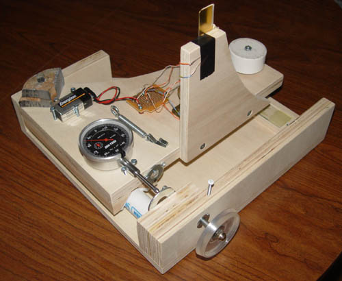
Figure 3: A slitless
Foucault tester for testing concave mirrors.
This tester was used to measure the shape, or "figure" of the primary
mirror and the test plate for the secondary mirror (more on this below).
The primary mirror refiguring was no different than a normal parabolic
mirror, except that it had a hole in the center! The subdiameter
lap that I made was made just large enough that it could be pressed
between
the hole and the edge of the mirror. At the beginning of a
figuring
spell, the lap was used gently after the press until it no longer
grabbed
when passing over the central hole. The severely undercorrected
outer
zones were corrected gradually, and the mirror was soon done with a
smooth
figure accurate to significantly better than 1/10th wave wavefront
error, according to my measurements.
Focault testing
was done with a six-zone Couder mask.
Here's
a photo of the coating being stripped off the primary mirror before
refiguring, and of the
subdiameter
lap being pressed into contact.
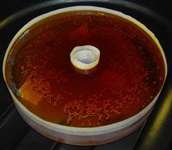
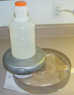
Figure 4a: Old coating
being stripped. Masking tape dam keeps the
chemicals from running off the sides, or down the hole.
Figure 4b: Subdiameter lap
being pressed under water jug and weight.
The secondary was the critical
component in the scope. It had to
have the right curvature so that the focal plane was located in the
proper place. This is important - moving the secondary in and out
can move the focal plane around and give more or less back focus if
necessary, but one should not deviate too far from the ideal spacing.
Moving the
secondary too far inward towards the primary results in
undercorrection.
Moving it too far out results in overcorrection. For this
adjustment,
1/8" of change in the spacing makes a big difference in star testing
results. The moral of the story is, get the secondary curvature
right, or you will have to redesign your scope!
The secondary mirror and grinding tool both began as 4" Pyrex
blanks.
With grinding, gradually one becomes concave (the test plate), and the
other convex (the secondary mirror).
Because I wanted to make more Cassegrain secondaries in the
future and other small mirrors, too, I built a small turntable that I
could sit comfortably at
while grinding or polishing. Cost was under $150. A
geared-down 1/3 hp DC motor drives
the turntable via a belt. The motor is powered via a variable
transformer
(a Variac) and a full-bridge rectifier, which converts the 120VAC from
the wall to anywhere from 0 to about 90VDC. I wired it up
myself. This homemade speed controller
spins the turntable anywhere from 0 to about 250 RPM. (I plan to
add
a driven arm to this machine very soon, so it can polish mirrors up to
about
13" in diameter for me while I watch!) As pictured, though, it
has a manual overarm. I hold onto the arm and move it back and
forth while the turntable turns the work. The top of the machine
is a
piece of formica-covered countertop that I had on hand, and the red
splash
pan is a water tub for farm animals, purchased for a few dollars at
Farm
and Fleet.
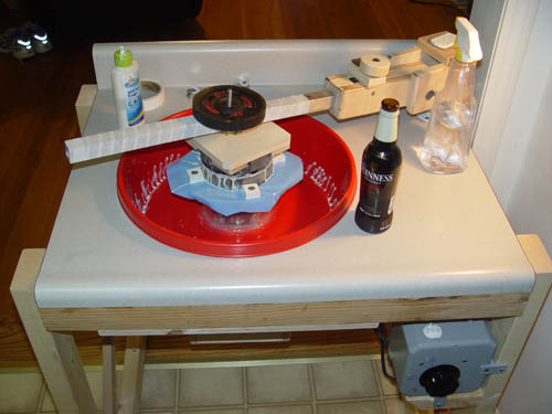
Figure 5: The turntable,
with manual overarm, polishing a 5" mirror.
All equipment on top of the machine is vital!
I ground the secondary mirror and test plate from 120 grit Carbo down
to 5 micron Aluminum Oxide, measuring their curvatures frequently with
a crude spherometer made from a pulley, some ball bearings, and an
inexpensive dial indicator.
The concave tool later became a test plate, a polished optical surface
that is figured to a concave hyperboloid that perfectly matches the
convex
hyperboloid that the secondary will become. Below is a photo of
the spherometer, sitting on a fairly flat surplus optical window,
zeroed and ready for measurement of the curvature of mirrors. The
large bolt is tightened by hand, and holds the dial indicator
stationary in the bore of the pulley. To the right are both 4"
and 5" test plates and secondary mirrors. The 4" became the
secondary for this telescope. (The 5" secondary later went into
our club's 16.25" F/12.5 Cassegrain - it was another large project in
it's own right. See my web site link at the end of the article
for more info on that scope.)
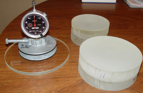
Figure 6: Spherometer being
zeroed, future 4" and 5" secondary
mirrors and test plates. (The 5" was for another telescope.)
The concave test plate
can be tested using the Foucault test, and figured just like a small
primary
mirror, however it has several times the correction of a parabola of
comparable
size and focal ratio. (For mirror makers, this one had about
four
times the correction of a 4" F/6 parabola - not too bad.) I
finished
figuring the test plate in a few evenings of work, and I noted that I
had
a small, slightly depressed ring just inside the edge of the mirror.
This
would be important later, when I was trying to make the secondary
mirror
match the test plate to within a millionth of an inch.
Once the test plate was done, I had to polish the secondary mirror out
without having the curve drift too far from the curvature of the
already-finished test plate. Using the machine, the secondary
polished out less convex than it should have been, so I had to use a
special lap to wear down the
outer part of the mirror until the curvatures matched approximately.
The
lap had some of the pitch carved out from the center, so that the edge
would
wear more than the center, thereby making it more convex.
After polishing sessions, the curvature of the secondary was compared
to that of the test plate
(both polished) using a simple Newton interferometer, which consists of
a few compact fluorescent lights, a diffuser screen, a red filter (for
lighting effects), and
a
two way mirror. This is homemade gear, costing about $40 to build
from plywood. It is NOT an expensive
commercial
interferometer. To perform a test to see how the mirror and test
plate fit, the mirror
and test plate are cleaned, and then placed in contact with each other
under
the interferometer. They settle into intimate contact if they
are
clean, separated by an air gap only a few wavelengths of light thick,
or
about
100 millionths of an inch. (That's why they must be clean!)
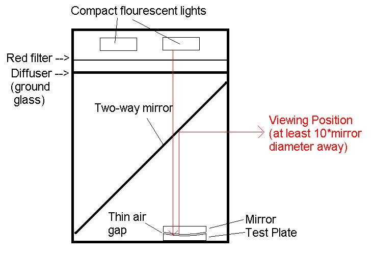
Figure 7: Diagram of simple
Newton interferometer. Convex mirror
sits on top of concave test plate, separated by a thin air gap.
The simple setup produces a fairly good source of diffused
monochromatic
light, which allows the differences between the secondary and test
plate to be observed in terms of interference "fringes", the dark bands
seen between bands of
red below. The spacing between each dark fringe represents 1/2
wave
of surface error (about 14 millionths of an inch for the red light used
here),
which is one wave of wavefront error. The fringes are viewed from
several feet away to avoid parallax errors, which distort the fringes
if you view them from too close to the tester.
In a nutshell, curved fringes mean there is work still to be done -
they
mean that the mirror and test plate don't match exactly. The
appearances of the
fringes
themselves means that the top piece is "tilted" with respect to the
bottom
piece. It is easy to observe the "squiggles" and curves in the
fringes.
In the photos below, where the lines curving to the right
represent
a high spot. Thus, in the first photo, a high ring exists at
approximately
the 70% zone, that is, 70% of the way from the center to the edge.
(This
is normal in figuring a Cassegrian secondary.) In the second
photo,
the outer areas are high. Photos are taken at a distance with a
digital camera - this is exactly how it looks to your eye when looking
into the tester.
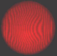
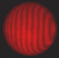
Figures 8a, 8b: Photos of
interference fringes during testing.
Fringes curving to the right indicate high spots.
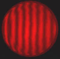
Figure 8c: Interference
test for finished mirror.
The fringes gradually get straighter, and the final result is shown in
Figure 7c. The larger "wiggle" in the fringes about
3/8"
inside the edge is due to a depression on the test plate, not the
secondary,
so the figure of the mirror turned out quite well. A perfect
mirror/test plate
match would show perfectly straight fringes. The test plate is
safely packed away in a closet, ready for use if I
ever need a secondary mirror with the same specifications.
With both mirrors finished, the optics were off to L&L Optical
Services for coating with enhanced aluminum. For this type of
Cassegrain, which has three mirrors, having 95% reflectivity (enhanced
alumimum) on each
optical surface provides about 86% light throughput, versus 70%
throughput for three mirrors with
89% reflectivity (standard aluminum). That's a big (almost 20%)
difference, and worth the extra cost.
Telescope Construction
While my primary goals for this telescope were high optical quality and
a convenient viewing position, I also wanted a telescope that I could
easily disassemble, and which would not take up too much space.
The solution for me was an open tube with oversized tubes at the
four corners of the mirror box.
The mirror box was made of 1/2" baltic birch plywood. It features
two baffles, one each near the top (front) and bottom of the box, which
fit in
dadoes (slots) that are cut in the inside of the box sides. The
box sides are joined at the corners with biscuit joints - slots are cut
in the wood which accept small wooden "biscuits". These biscuits
align
the joint and strengthen it. When glued with good quality wood
glue, the biscuits and dadoes form a very strong box with no other
fasteners required. This means no screw or nail holes to patch.
Here's a photo of the mirror box, viewed from the rear, assembled
without glue to check the
fit of the parts. Note the holes in the front baffle to
accomodate the 1.5" diameter aluminum poles. The edges of
the holes don't line up exactly with the insides of the box - this
bends the poles slightly when the scope is assembled, and thereby
creating a
stiffer tube structure. The poles are stuffed with
styrofoam
peanuts to damp vibration, and have threaded inserts in each end.
The threaded inserts screw on to four bolts inserted in the the
back baffle in the mirror box. The heads of the bolts are visible
at the four corners of the back baffle (nearest in this photo).
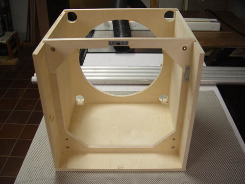
Figure 9a: Mirror
box partially assembled. Top of box has been removed.
Here is another photo of the box, again without the top, with the poles
inserted and threaded onto the bolts. The metal bracket at the
top of the back baffle serves to reinforce the attachment point for the
mirror cell.
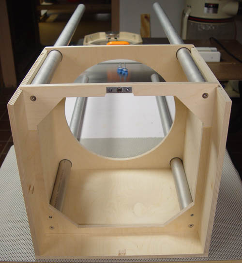
Figure 9b: Mirror
box partially assembled. Poles installed.
The mirror cell was made mostly of 3/4" strips of baltic birch plywood,
laminated together in places for strength. Its triangular frame
is
attached to the back baffle in the mirror box (above) with a bolt and a
type
of rod end that allows a bolt passing through it to pivot with very
little
mechanical slop. The bottom two attachment points also employ the
same
part of rod end, but these points are movable to allow for collimation.
Threaded knobs allow tweaking of the primary collimation at the
eyepiece, using a star.
The primary mirror is supported with a four-point mirror cell. A
photo of the nearly finished, painted mirror cell is below. The
top two contact points (white plastic squares) are mounted on a piece
of aluminum tubing which is supported at the center - this is
effectively a teeter-totter. The bottom two points are fixed.
This supports the full-thickness mirror enough to prevent
detectable flexure of the primary mirror. The two L-brackets that
support the bottom of the mirror were later replaced posts made of 1.5"
diameter Nylon. A teflon contact point was added to the top
bracket, and PVC mirror clips were fitted to all three brackets to keep
the mirror in the cell. In this type of cell, the mirror clips
move with the mirror, so the mirror need not have lots of room to
rattle around.
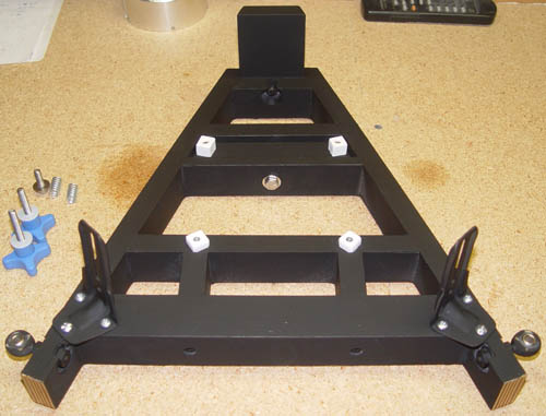
Figure 10: Mirror
cell. 4-pt. support is enough for the full-thickness primary.
My goals for the secondary cage were light weight, low wind profile,
and minimal diffraction caused by the secondary support. This
meant using a spider that was made of thin wire, something I had never
seen done with a Cassegrain telescope. Additionally, the spider
attachment points on the central hub are offset to resist rotational
vibration of the secondary. (The
offset spider concept was introduced decades ago in Texereau's book,
"How to Make a Telescope"; still, few people realize its
advantage.)
For the secondary cage, I chose to make a square front board with a
circular
hole to define the telescope aperture, reinforced with an octagonal
frame that would serve to anchor the spider. The four
poles attach at the corner of the squares, sitting in recessed
holes.
The secondary cage assembly was glued together, and this proved
fairly
complicated. Here's a picture while the glue dried.
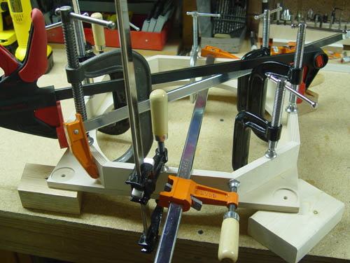
Figure 11: Assembly of
secondary cage. You can never have too many clamps....
The forest of clamps was removed, and holes were later drilled in the
octagonal frame to lighten it and allow wind to pass through.
Before this, though, the holes for the four stainless eye bolts
that anchor the spider were drilled. As the spider is of the
offset variety, these holes are not equally spaced around the octagon.
The central hub consisted of two 3.5" x 1" x 0.25" aluminum bar,
connected by two stainless bolts which were threaded all the way to the
countersunk head. The bars were locked onto the bolts with nuts.
Four small screws serve as anchors for the ends of the two pieces
of wire that form the spider. A piece of baltic birch is attached
to the aluminum bar. Three adjustment screws pass through the
wood and secure the aluminum secondary holder. Here is a closeup of
the central hub. The front is at the bottom.
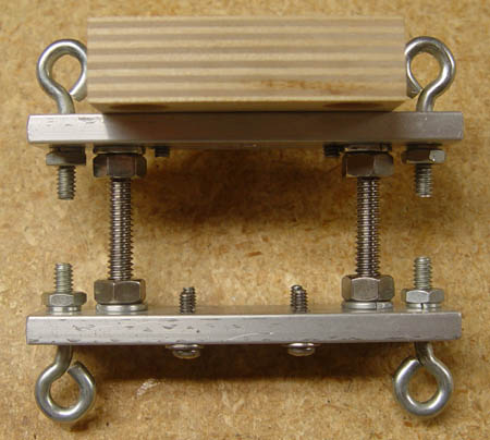
Figure 12: Central
hub of the wire spider. Secondary mirror
attaches to wood block at top.
To string the spider, a jig was made consisting of one strip of baltic
birch, with holes drilled so that the central hub could be
securely fastened to it. Stainless steel wire, 0.015" thick, was
secured under one screw and washer on the front of the central hub
assembly. The screw was tightened securely, and the wire was
threaded through one of the eye bolts on the front of the central
hub. It then passed through an eye bolt on the secondary cage
(wrapping completely around it once),
back to the central hub and through the eyebolt on the back side
of the central hub, through another eye bolt on the secondary
cage, and finally through the eyebolt on the back of the central
hub. The wire was pulled fairly tight, and secured under another
screw and washer. This formed the bottom two legs of the offset
wire spider. The sequence was repeated for the top two legs,
with another piece of wire. The wire was then de-tentioned by
loosening
the eye bolts on the secondary cage, the jig removed, and the wire
re-tightened.
Thus, the spider was completed. Here's a photo of the
secondary
cage, central hub, and spider jig before stringing.
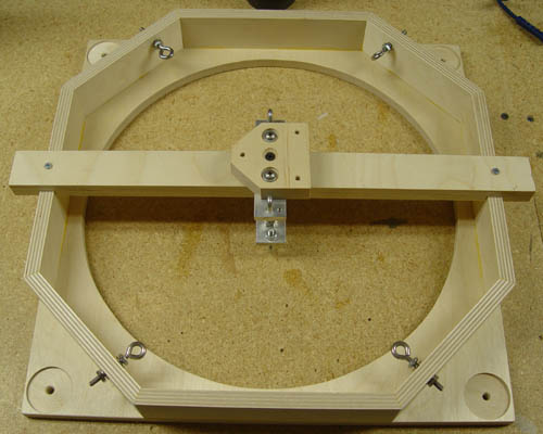
Figure 13: Secondary cage
and spider stringing jig. Ready for wire.
The next photo shows a closeup view of how the wire was wound and
secured on the central hub. Where the wire passed through the
screw
eyes on the cage (seen in the photo above), it was wrapped once around
the eye before going back to the hub. The two black knobs are
used to adjust the tilt of the secondary holder. Compressible
rubber washers are placed between the aluminum disk seen in the photo,
which is part of the secondary holder, and the piece of wood.
Later, a strip of aluminum was bent around
the aluminum disk, a lip was bent over on one side, and it was secured
to
the disk with screws. The secondary sits inside this assembly,
with
polyester batting behind it to press it gently against the lip, much as
is done with many secondary holders in Newtonian telescopes.
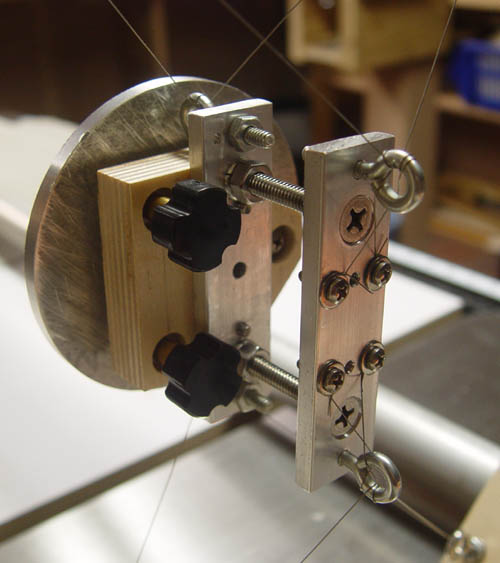
Figure 14: Closeup of
central hub, suspended by wire spider.
Finally, here's a photo of the finished secondary cage, complete with
painted secondary holder, and a painted and stained cage. The
blue
knobs attach the poles (by threading into the threaded inserts in the
tubes),
to which the cage is attached in the photo. Note holes in the
sides
for weight reduction.
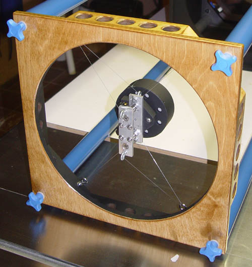
Figure 15: Finished
secondary cage. Blue knobs thread into inserts in
the poles. Unpainted aluminum in hub is not visible to the
optics.
For the tertiary mirror holder, I wrapped a thin piece of aluminum
sheet
around a 1.5" dowel, and used a chop saw to cut it off at a 45-degree
angle. The aluminum was slid down the dowel a little bit, and a
lip was created around the 45-degree hole. This would hold the
tertiary mirror in. A metal plug was inserted into the other end
of the aluminum, and a bolt passed through and angle bracked and into
the plug, securing it to the tertiary assembly.
The tertiary assembly tilt is adjusted via sections of threaded
rod
that can be accessed from the rear of the telescope. These act as
push bolts, and there is a central pull bolt attached to the tertiary
holder assembly. (Tyipcally,
this
mirror is quite stable and needs no adjustment.) A photo of the
tertiary
holder is shown below, installed in the scope, in front of the slightly
dusty
primary. The round disk attached to the two standoffs is a ring
baffle,
which blocks stray light from reaching the tertiary. This is much
simpler than a traditional round baffle, and is much easier to
implement. A classic "pipe" type baffle would probably work
slightly better, but its inside must be carefully baffled to prevent
reflections at grazing incidence. For my use, this baffle works
well.
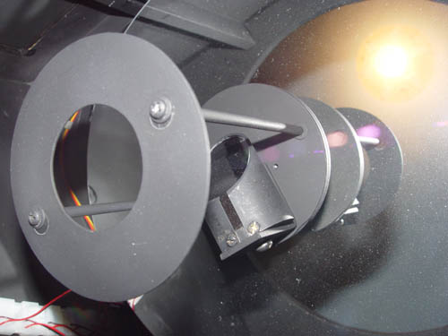
Figure 16: Tertiary
mirror in 45-degree holder. Ring baffle is to
the left. Light from the secondary passes through the hole in the
ring. Disk behind tertiary is plexiglass, painted black.
The various wooden parts of the telescope were stained and
polyurethaned. Internal parts were painted Krylon Ultra-Flat
Black. Teflon and formica were installed on the rocker box, and
the side bearings were bolted on the mirror box. The side
bearings are 1" thick, composed of two thicknesses
of 1/2" baltic birch. 1/8" x 1" aluminum bar stock was bent
around
the outside edge with waterproof glue underneath. Screws secure
the
bearing at various points around the circle. The glue fills in
any
gaps under the aluminum, filling in any slight void and eliminating any
tendency
of the scope to "bounce" when move small amounts in elevation.
Below
the masking tape layout is shown for the side bearings, with the
balance
point of the scope marked. Four bolts secured each side bearing.
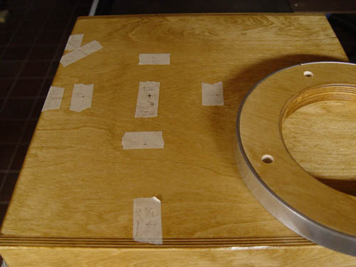
Figure 17: Marking the
balance point and installing the side bearings
The focuser is a blue-anodized 2" Crayford model from Moonlite.
It sits on top of a wooden platform on top of the mirror box. It
is smooth in operation, and the blue color matches the blue of the
tubes and the collimation knobs. This blue color goes well
with the golden color of the woodwork. The focuser can be seen in
the photos of the assembled scope below.
First Light
First light happenned in my driveway near the beginning of April of
2005. I set the rocker box on a piece of plywood, which was
placed directly on the concrete of my driveway. I knelt to look
in the eyepiece, and located a bright, poorly collimated image of the
waxing moon. Two friends looked too. I realized it was time
for some serious collimation work, installation of light baffles, and a
folding platform to privide that convenient viewing position that I was
so fond of. The equatorial platform arrived soon afterward, so it
was time to build a support platform for it.
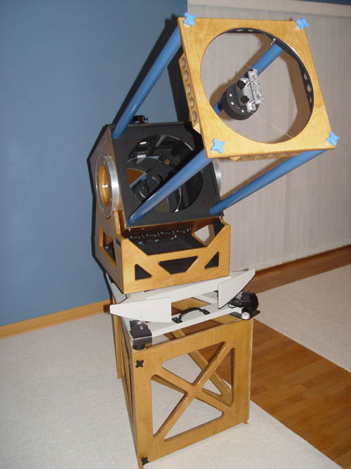
Folding Platform
The folding platform was my idea and creation. It folds up (to
about 24" x 20" x 5") for
easy storage. When unfolded, two threaded knobs are installed,
locking the
sides
together. It is triangular to match the shape of the equatorial
platform
that I bought from Tom Osypowski; with the equatorial platform sitting
on
top of it, it is extremely rigid, and does not vibrate much at all.
Here are
photos
of the platform being unfolded. Note the selective removal of
wood with bracing remaining intact.
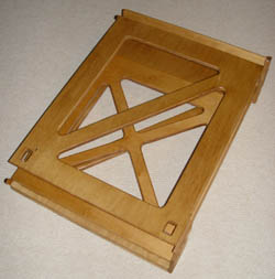
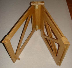
Figures 18a, 18b: Support
platform folded, and partially unfolded.
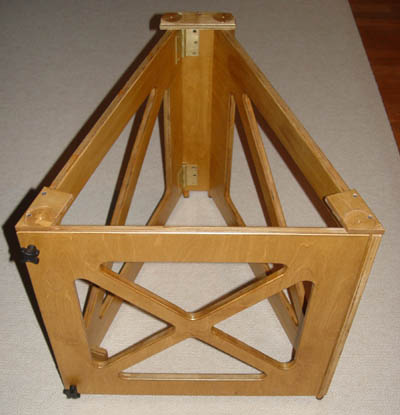
Figure 18c: Support
platform with locking knobs installed.
The space inside the platform is a very convenient place to place the
17
amp-hour battery (a "jump start" power pack) that I use to power my
telescopes. It sits completely out
of
the way, and no one can trip over the cords!
Pole Case
While I was in a building mood, I made a case for the four poles.
It
was made of 1/4" and 1/2" Baltic Birch. I made the box, and glued
the
sides to both the top and bottom. Then I cut the lid off with my
tablesaw,
ensuring a perfect fit of the lid. Here's a photo of the tubes in
the
box, complete with some strips of weatherstripping to keep the poles
from
rattling. (The end of the poles that goes inside the mirror box
is
painted flat black, the rest is Rust-Oleum Royal Blue.)
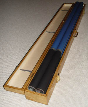
Figure 19: Pole
storage box, poles inside.
Ventilation
The full thickness primary mirror needs cooling. There is no
alternative.
So, I added six 60mm, double-ball-bearing 12V fans to the
mirror
box. Four push air up across the primary from the bottom, and out
through
doors in the top of the mirror box. Two fans move air across the
back
of
the mirror from the top corners of the mirror box. Here's a photo
of
the fans blowing across the primary:
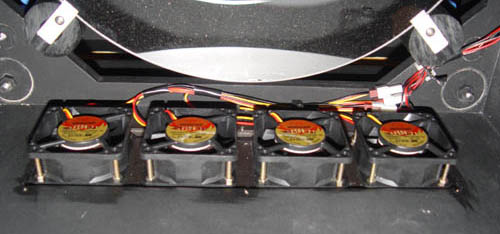
Figure 20: Ventilation fans
for front of primary mirror.
Here's a photo of the back of the mirror box, showing the tertiary
support
framework (T-shaped square tubing), tertiary adjustments near the
center,
and the two fans in the upper corners:
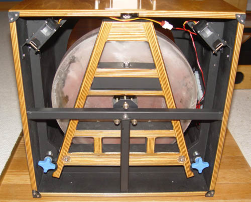
Figure 21: Back
of mirror box. Ventilation fans at upper right and
left. Tertiary adjustments at center. T-shaped structure is
the
tertiary support, made of steel tubing. Blue knobs are for primary
collimation. Back of box is open for better ventilation.
The six fans result in much faster equilibration, and improved images
during
cooling. No vibration is noted from the fans at high power.
I have experimented with a fan blowing on the secondary from below, but
I haven't concluded whether or not it is beneficial.
Collimation
After adding flocking paper to the focuser (which resulted in the
single
largest increase in contrast of any step that I took) prevented
me from
inserting
my 2" laser collimator all the way into the focuser. So, I now
use
a 1.25" collimator. First, the tertiary is
aligned
to place the laser in the center of the secondary (this usually does
not
require adjustment). Next, the secondary mirror is adjusted so
that
the reflection of the laser returns to exactly where it originated.
Finally,
the primary mirror is adjusted while viewing a star in the eyepiece, to
eliminate
coma. The two blue knobs in the picture above are the primary
collimation adjustments.
That's all there is to it. I can have the scope collimated in a
few minutes, provided I can find a star to align the primary
with. (A barlowed laser would probably allow daylight collimation
of all the components, but some tweaking of the primary might be needed
once it got dark. I hope to try this soon)
Performance
The performance of this telescope has exceeded my expectations.
With
a 32% obstruction ratio, I expected planetary detail to be washed out,
and
reduced from what I was used to seeing in my Newtonians. I was
wrong,
especially after a little collimation practice!
Planetary detail was excellent. Saturn was sharp at 450x when the
seeing
permitted. Jupiter showed numerous bands and subtle detail.
I
could discern color in one of Jupiter's moons as it transited, and
could
follow the disk across. The central star in M57, the Ring Nebula,
flickered
in and out with the seeing conditions. The double-double (Epsilon
Lyrae)
was easily split, and diffraction rings were visible when the seeing
permitted.
Even a wheelchair-bound fellow club member was able to catch
views
of some objects (a shorter platform would have allowed him to see
nearly
all
of them), and my friends enjoyed sitting comfortably and observing.
For
public events, the intimidation factor is simply not there, compared to
large
Newts with ladders. One interesting phenomena is watching people
approach the scope; they walk over, staring at the secondary,
apparently suspended in midair! Once they get close enough they
can see the wires, and then marvel at how thin they are (0.015").
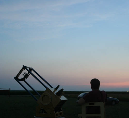
Here's a photo of the scope set up for
observing in the flatlands of Illinois, waiting for Jupiter to emerge
in the twilight. Not shown in this photo are the trap doors that
allow air to escape after being blown across the primary by the
fans. Note the Rigel Quickfinder on the mirror box - this is all
I need to find objects with a low-power eyepiece.
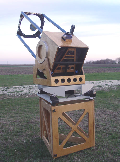
Ready for observing. Wish
those clouds would dissolve....
Setup and teardown require 15 and 10 minutes, respectively. All
components
of the telescope (including the equatorial platform) will fit behind
the back seat of my Subaru Outback,
along
with eyepiece cases and a tool box. Because of this, it gets used
a lot.
My conclusion is that this instrument
is a resounding success. Of
course,
my mind has already wandered to future scopes! An 18" or 20"
Cassegrain
is within reach, but it will require a faster primary (F/3.5 or less).
Such
a scope can still be extremely portable, and will have the same viewing
position
- feet planted on the ground. A thinner primary is a necessity
for
cooling and weight reasons.
In closing, I'd say that I am very happy with what I have learned in
the
construction of this telescope and its performance. I hope
that
in the future it inspires others to try the design, and shows that
Cassegrains
don't have to be inferior in terms of optical quality. If the
optics are top notch, then a scope with a well designed mechanical
structure will yield excellent images.
I'd like to thank all my friends for their
support and encouragement, my girlfriend for her understanding, John
Pratte for his help welding the tertiary support frame, Dick Wessling
for his advise regarding the optics and design, and Ed Jones for double
checking my calculations of the optical system.
Thanks for reading. Here's one last photo of the telescope and me
as daylight fades....
Photo
by John Stone
Build a Cassegrain! It's fun!
Mike Lockwood