A modern guide to mirror
support
The
best ways that I have found to properly support primary and secondary
mirrors with maximum stability and a minimum of other issues
All images and text Copyright Mike Lockwood, 2016
Have you ever wondered if your mirror cell is supporting your mirror as well as it could be?
This is a very important question if you care about the quality of the images that your telescope produces. Most mechanical problems in mirror cells cause degradation in images and telescope performance that are much larger than typical optical errors, so it is wise to invest some thought, time, and effort to learn how to properly support your mirrors and install them in their holders. To say it another way, if you see major distortion of star images at low power, and know that your collimation and eyes are not the culprit, then there is a good chance that you have a mirror support issue.
 If you want some additional
background before continuing here, an article that I wrote
that explains how to diagnose problems in reflecting telescopes can be found here.
That article was based on nearly a decade of my experiences
using, building, screwing up, and fixing telescopes. I strongly
recommend
reading it and going through some of the steps and
tests that it describes to learn and isolate the problems within your
telescope. Then if you find mirror support issues are the likely
culprit, the rest of this article will help you out. An
article about optics that were re-tested due to some support issues can be found here.
If you want some additional
background before continuing here, an article that I wrote
that explains how to diagnose problems in reflecting telescopes can be found here.
That article was based on nearly a decade of my experiences
using, building, screwing up, and fixing telescopes. I strongly
recommend
reading it and going through some of the steps and
tests that it describes to learn and isolate the problems within your
telescope. Then if you find mirror support issues are the likely
culprit, the rest of this article will help you out. An
article about optics that were re-tested due to some support issues can be found here.There really is no one good source for modern mirror support information. Books have been published in the past, and even recently, give information on the topic, but much of the information is out of date. Other advice steers those who are looking for the highest quality mirror support methods in, what are in my opinion, the wrong directions. Some older mirror cell designs are very close to guesswork, and should simply be avoided.
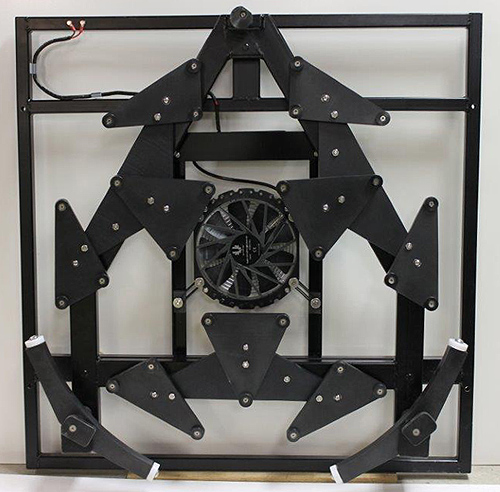
The picture at right here (courtesy of John Pratte) is a 32" cell by JPAstrocraft, and it has many of the desirable features that will be discussed later in this article - hard plastic contact points, modern edge supports, and a separate moving frame that carries all of the parts that touch the mirror so that they do not change position on the mirror as the collimation is adjusted.
Why should you read this article and take my advice? Because I have been blamed for the effects of inadequate mirror cell designs, and instead of simply blaming the mirror cell maker and going on with my work, I have devoted a lot of time to figuring out what is going on. It has been a fascinating learning experience. I have done more mirror cell testing in the shop and under the sky than any other vendor that I know of, optician or telescope builder. I have fixed and helped clients fix many mirror cells and have learned a great deal. It is in my own self-interest to do this, because if someone sees astigmatism in their telescope, naturally the first person they blame is the optician, even though every mirror that I make is tested thoroughly for significant astigmatism and other aberrations several times before it leaves my shop.
So, based on my experiences using and fixing many types of mirror cells and many secondary holders, I have written this article to try to share what I have learned. I am sharing this information freely, and I hope that this article is a good resource for modern mirror support information.
I consider carefully which telescope vendors that I work with based partly on how they build their mirror cells and secondary mirror supports because I care about my clients' experiences, and because I am selfish. I simply don't want my thin mirrors placed in certain types of cells because I know from very costly, time-consuming experiences that they may seriously degrade the performance of the optics. When this happens, even if the owner knows the real cause of the issues, others will look through the telescope, not knowing the issues, and it will give them a bad impression of my work. I encourage telescope builders and mirror cell makers to take the lessons in this article to heart for their interests and for mine.
In the many telescopes that I have evaluated, most of the time the supports under the back of the mirror are working properly, assuming that one uses appropriate contact points, that you have your triangles cut and attached accurately, and that all of the triangles, pivots, etc., can move and tilt freely. This should be easy to verify by first making sure that all of the triangles contact the mirror. Next, lift the mirror slightly away from the triangles and verify that they all move freely. If the contact points are even weakly stuck to the mirror or seem to bind when moved, those issues should be fixed immediately.
Other basic rules of mirror support are:
1) Do not glue
a mirror to a support unless you know exactly what you
are doing.
Mirror cell designs created by PLOP do not take into account all of the
forces that will be applied to a mirror which is glued to the cell and
is not pointed at the zenith. Many factors
determine whether
gluing will result in holding a mirror without significant distortion,
such as 1) glass type, 2) type of material that the mirror is glued to,
3) type of glue used, 4) thickness and shape of glue bond, 5)
temperature
range that the telescope is used in, 6) distance separating areas of
glue, 7) thickness/design of the mirror, and 8) orientation of the
mirror with respect to gravity. To say it simply, it is
complicated, and I don't recommend it for most mirrors, especially
those over 8" in diameter.
2) Do not ever "pinch" a mirror in a support. It should NOT be snug - there should always be slight clearance around it in all directions so that it can move slightly in the cell. To verify this, make sure the mirror "rattles" in the cell.
3) Assuming the back of the mirror is fairly smooth, use low-friction contact points made from hard plastic, such as Delrin or Nylon, and machined smooth to match the back of the mirror. Teflon can cold-flow, and thus is not the best material for this. Felt pads and cork pads are strongly discouraged, as the friction that they cause will distort the shape of larger and thinner mirrors. Put the mirror is in the cell and make sure that it contacts all of the rear contact points and has slight freedom to move (see #2 above). Low friction is the goal for rear contact points.
4) Make sure that all cell parts that move or pivot do so with little resistance and friction, and make sure that the mirror is centered accurately in the cell over the triangles.
5) Do not become obsessed with your PLOP designs - the program is not perfect and does not account for all of the factors (such as friction) and forces that come into play while supporting a precise piece of glass. It is often easier to execute an 18-point cell with excellent mechanics than a 27-point cell, so if the differences are small, choose the simpler cell design and build it with care and precision.
6) Pay lots of attention to the mechanical execution of the cell itself, and buy quality parts, such as spherical bearings, bushings, stainless fasteners, etc., that will not rust or degrade with exposure to water.
7) One characteristic/feature of a well-made cell is that the mirror can be rotated in the cell by hand when the telescope is not pointed low. I have done this with 28" mirrors in good cells with little effort. A sling or glue will prevent this from being done.
Let's discuss some rear support point basics in more detail. I can recall a few cases where I saw a simple mechanical problem with the rear support, such as a bolt that interfered with the motion of some triangles, but in general the rear support is not too problematic if it is made to a reasonable standard of craftmanship and is tested with the mirror in it to make sure all of the triangles contact the mirror.
Below is an image, courtesy of John Pratte, of a 24" mirror cell made by JPAstrocraft. These are the type of contact points that I will discuss now.
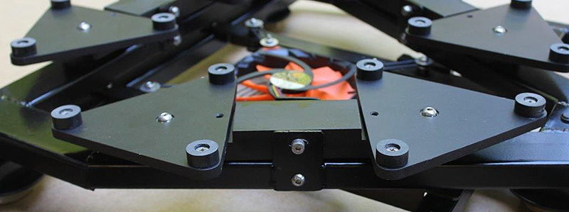
The primary mirror should rest on hard plastic contact points that have relatively low friction. Polished metal will work too, provided there is no chance of the mirror bouncing on them, as it might do in transport. I prefer and recommend Delrin contact points, or Nylon if Delrin is not available, about 3/4" to 1" in diameter, about 3/16"-1/4" thick, and attached to the triangles with machine screws. You might think that Teflon is the best material, but Teflon actually cold-flows and can actually slightly adhere to the back of the mirror if it is not smooth, and this is why I recommend harder plastics.
 Also, as mentioned
above, felt pads,
furniture slides, and cork
have much higher friction and can stick to the back of the mirror,
which can cause distortion as the telescope is moved around or as the
temperature changes. They also compress slightly under
load, causing slight collimation shifts.
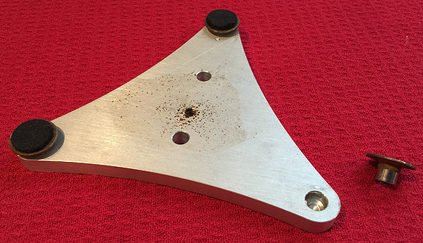
The felt furniture slides may work fairly well at first, but they will
absorb moisture and dirt and will eventually stick. They can
rust, as seen in
the image at right which was provided by one of my clients. So,
plastic support pads have more than one
advantage.
Also, as mentioned
above, felt pads,
furniture slides, and cork
have much higher friction and can stick to the back of the mirror,
which can cause distortion as the telescope is moved around or as the
temperature changes. They also compress slightly under
load, causing slight collimation shifts.
The felt furniture slides may work fairly well at first, but they will
absorb moisture and dirt and will eventually stick. They can
rust, as seen in
the image at right which was provided by one of my clients. So,
plastic support pads have more than one
advantage.I have actually seen, with my own eyes, intermittent and unpredictable astigmatism in a 32" telescope that was caused by felt pads/slides used for contact points, so I know that the phenomena is real. Lifting the mirror up slightly and setting it back down would release the stiction, and then the shape of the stars would return to round. After moving the telescope around the sky, the stiction would return, and the mirror would need to be un-stuck yet again to provide its best performance. The owner of the telescope replaced the felt pads with Delrin and the problem disappeared.
This distortion was readily visible at medium power, so it was likely 1/4-wave or more in amplitude. Small forces create significant distortions in today's modern, fast-cooling, thin mirrors. In short, it is my opinion, supported by experience, that cork and felt are outdated mirror contact materials for the modern, high-quality telescopes.
If you replace your support points with plastic, for best performance I recommend using fine sandpaper to sand each individual triangle, with contact points attached, against a very flat surface so that the surfaces of the support points on each triangle are co-planar. Simply tape the sandpaper to something quite flat and rub the triangle on it until most of the points have been sanded. Go through more than one grade of paper if you need to. This sanding ensures that most of the surface of each contact pad will contact the mirror. This improves the accuracy of the effective location of the contact points, and distributes the mirror's weight over most of the pad, thus lowering friction between the mirror and support points, which is both good and necessary.
As a final very important check of the rear supports, with the mirror sitting in the cell on the triangles, make sure that all of the support points and triangles contact the mirror, and again verify that the mirror is centered in the cell, and that all of the triangles are rotated properly and positioned according to the design.
Update, September 2016: For more information on rear support pads, see this installment of "In the Shop", which describes some modifications that I made to my Starmaster 20" f/3.0 cell and a few things that I learned along the way.
Primary mirror edge support
The most neglected and least understood part of a mirror cell is the edge support, the part that keeps the mirror from sliding out of the cell when the telescope is pointed anywhere other than straight up. The edge support is critical to the performance of the telescope, but many amateurs do not pay much attention to it, or they get it quite wrong. It seems quite simple, but due to the mechanics involved, it must be done carefully.
This adventure in edge support started a number of years ago while John Pratte was building a 25" telescope. John had ruled out the use of a sling from the start, and with the edge support schemes accepted at the time we saw distinctly triangular and astigmatic stars as the telescope was pointed lower in the sky. For John 25" telescopes (see link to The Twenty-Five), he and I discussed and debated how to design and build the edge support for the cell. All we knew for sure was that it had to be rigid enough to hold collimation at all altitudes, and it should not cause noticeable degradation of star images at any altitude.
My first recommendation with a mirror cell, and something that John had already decided on well before, is to use a moving-frame type cell. In this design, everything that touches the mirror (triangles, edge support, retaining clips) is attached to one frame and is moved by the collimation bolts, which move it relative to another frame that is bolted to the mirror box. Starmaster Portable Telescopes has used this design with good results for years with a whiffletree edge support design that they developed quite early in their production.
The moving-frame cell can be seen clearly and is explained on John Pratte's (JPAstrocraft) mirror cell page. When collimation is adjusted, everything moves with the mirror. In less advanced cells, only the support triangles are moved, and everything else is fixed. Thus, the sling or edge support can become misaligned and the mirror can become pinched against the retaining clips, both of which will cause star images to become distorted. It costs more to make a moving-frame cell, but I believe it is well worth it.
As I mentioned before, we had decided against using a sling for edge support in the 25". Another reason for this is because even with the moving-frame cell design, it is difficult to take the mirror out of the cell and put it back in and get the sling back to exactly the right spot. John removes the mirror from his 25" telescope when transporting it, so this is a major consideration. Another reason is that a sling allows the mirror to shift laterally (side to side), which throws off collimation. In hindsight, I wish we had tested it for comparison purposes, but I do know from other testing experience that slings can cause a mild amount of astigmatism, but they can be made to support the edge of a mirror reasonably well if care is taken.
In my experience, a sling is better than the worst configurations of edge support that we tested below, but not as good or as mechanically stable as the best configurations. I only recommend slings for mirrors 36" and larger due to ease of implementation, and that may change in the future as I learn more.
If you must use a sling, if your cell is a non-moving-frame type make sure that 1) it is a cable sling, not a seat-belt type, and 2) that it uses linear bearings that allow the sling to move as the mirror moves (as it does when collimation is adjusted). Howie Glatter sells cables and bearings which are a great improvement. However, if the linear bearing axis is not parallel to the optical axis when the mirror is collimated (i.e. the linear bearings point in a direction that is not parallel to where the primary mirror is directing light), then the sling will not be perfectly aligned with the plane of its center of gravity of the mirror, and some non-ideal force will be exerted on the mirror that may cause astigmatism.
If you do not have Howie's sling and you do not have a moving frame cell, then after collimating you can carefully adjust the sling so that it lies on the plane of the center of gravity of the mirror. If you can do this and collimation does not shift much when you reassemble the telescope, then the sling can provide quite good edge support. However, you should periodically check the sling position to make sure it hasn't moved.
If you are using a sling and the cell does have a moving frame, the linear bearings are not necessary if the sling is set up accurately along the plane of the center of gravity of the mirror. One should take care in doing this, and measure carefully. However, once it is done, this will provide fairly good edge support. This is the method that I recommend for supporting large (36"-48") thin mirrors in a conventional type of mirror cell. Other more complicated designs can also be considered here, but they are beyond the scope of this article.
However, in my opinion, a sling is an outdated edge support method for most thin mirrors up through 32" in diameter, and a non-moving frame mirror cell is an inferior type of mirror cell. I recommend that modern high-quality optics from the best sources, especially thinner optics, should be supported by a well-made, moving-frame cell that uses hard plastic contact points or other types of low-friction contacts. They are the least trouble and work the best. This opinion is based on my own considerable experience and testing of many mirrors and telescopes.
In the development of his 25" mirror cell, eight different types of edge support were devised by John and myself. I had a 25" f/4.0 mirror that was nearly spherical prior to figuring, so we could easily use the mirror in the cell in my shop to test this mirror at its radius of curvature and see how the edge support distorted it when the mirror was up on edge. Not having an interferometer at this time, I used my artificial star tester as a source and photographed the return "star" images. Looking at the artificial star images at focus was the best way to judge how the edge support was working. It was the lab version of viewing a star near the horizon with a telescope, in the nearly perfect seeing of my shop.
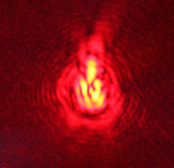
The results for all eight edge support methods are summarized in the table below. In the left column, a description is given of the type of edge support. The middle column shows a close-up photo of half of the edge support - a similar support is on both sides of the mirror. The right column shows the star image that was observed.
A perfect spherical mirror with perfect edge support would have produced a perfectly round spot with rings around it. However, the mirror was not perfectly spherical, and no edge support works perfectly. Generally, though, the smaller the star image and the more round it appears, the better. Also, a lack of "structure", or definite shape, such as triangularity, spikes protruding from the image, etc., is better. Keep in mind that the "star" images shown here are seen in much greater detail than those that would be seen after being blurred by the atmosphere. So, this is a very strict, revealing test that I employ on nearly every mirror that I make to test for astigmatism and other issues.
| Description |
Edge support photo |
Artificial star image |
| 1)
Two round Delrin rods,
separated by 90 degrees of angle, on either side of bottom of
mirror. Contact is on a line along the whole edge of the mirror
if the rod is square to the mirror. Rod is reinforced with metal frame to prevent flexure and maintain collimation. Safety clip seen at front of mirror. |
 |
 |
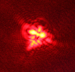
| 2)
Two round Delrin rods,
separated by 90 degrees of angle. Instead of the rod contacting
all the
way along the mirror's edge, a narrow raised area contacts the mirror
at the center of gravity (COG) of mirror. Rod is similarly reinforced as above. Safety clip is more clearly seen. The star image produced by this support actually reminds me of a devil with horns and a tail! |
 |
 |
| 3)
Conforming Delrin
blocks,
separated by 60 degrees. Curve in block was machined to match
edge of mirror. Blocks are made of 1"-thick Delrin. |
 |
 |
| 4)
Conforming blocks as above,
separated by 60 degrees of angle. Curve in block was machined to
match
edge of mirror. Blocks are made of Delrin. Soft felt pads were adhered at ends of blocks. Difference and improvement from non-pad configuration was visible, but not major. |
Same as
above, but with
soft felt pads at the ends of the block, some improvement seen. |
 |
| 5) Conforming blocks, separated by 90 degrees of angle. Curve in block was machined to match edge of mirror. Blocks are made of Delrin. | 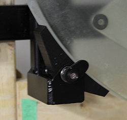 |
 |
| 6)
Conforming blocks,
separated by 90 degrees of angle. Curve in block machined to
match edge of
mirror. Soft felt pads were adhered at ends of blocks. Difference from non-pad configuration was visible, but not major. |
Same as
above, but with
soft felt pads at the ends of the block |
 |
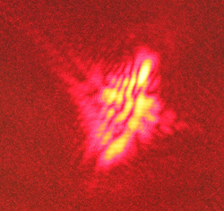
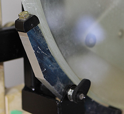
| 7)
Whiffletree - contact with the mirror is along
a line on the machined plastic pad. Pads are at the end of the
whiffletree, and are made of black Delrin. Four support points
are separated by angles of 45 degrees. Test image showed slight triangularity, but is pretty good. However, in-telescope testing showed astigmatism as the altitude changed because the mirror could not slide up and down against the edge support. Friction needed to be reduced further, thus the idea for configuration 8 below.... |
 |
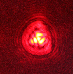 |
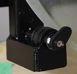
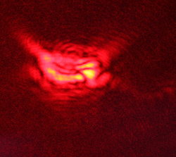
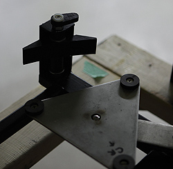
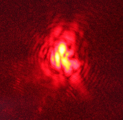
| 8)
Whiffletree, contact on plastic rollers (with internal metal ball
bearing) at the ends of the
whiffletree, contacting at COG of the mirror. Four support points
separated by 45 degrees. Star image was the most concentrated of all configurations tested, and showed absolutely no astigmatism in a telescope. (The flare in the image at right was due to an air current.) The rollers cannot pull on the mirror in the direction of the optical axis, which is a major advantage as the telescope is moved up and down and the rest of the cell flexes subtly. This was the WINNER. |
 |
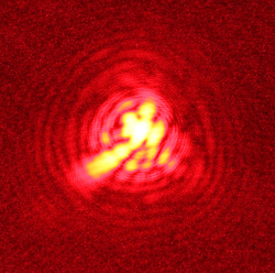 |
The best performer was configuration 8, the whiffletree with nylon rollers as contact points. Again, these rollers have internal metal ball bearings so they turn freely. The decision was made by observing the structure of the image that was formed in the lab test, and by observing using both whiffletrees in a telescope under the sky.
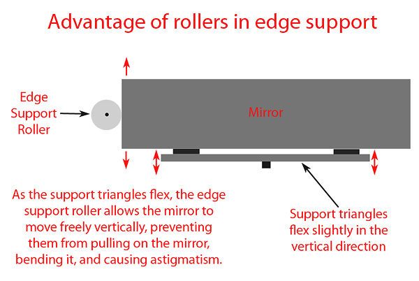 In choosing the best edge support
scheme, one
also must take into account the telescope's motion. As the
telescope moves up
and down in altitude, the metal of the support triangles and structure
flexes very slightly, and the mirror
moves down in the cell by tiny amounts. As this happens, if the
edge support is fixed, it will push or pull on the mirror
very slightly, which is sufficient to bend it enough to affect images
seen through the eyepiece.
In choosing the best edge support
scheme, one
also must take into account the telescope's motion. As the
telescope moves up
and down in altitude, the metal of the support triangles and structure
flexes very slightly, and the mirror
moves down in the cell by tiny amounts. As this happens, if the
edge support is fixed, it will push or pull on the mirror
very slightly, which is sufficient to bend it enough to affect images
seen through the eyepiece.The edge support roller rotates slightly as the telescope moves up and down, and does not allow the edge support to pull on the mirror. If the edge support is positioned properly, the only force applied is into the mirror, towards its center, along the plane of the center of gravity of the mirror. Configuration 7 was quite good, but when the telescope was moved up and down in altitude, the mirror was indeed found to "hang up" on the edge support as the other cell parts flexed slightly, and this caused significant astigmatism. To solve this problem, the rollers were added as you see above in configuration 8.
Thus, making this decision required in-depth testing both in the shop and in the dynamic structure of the telescope itself. It was well worth the time.
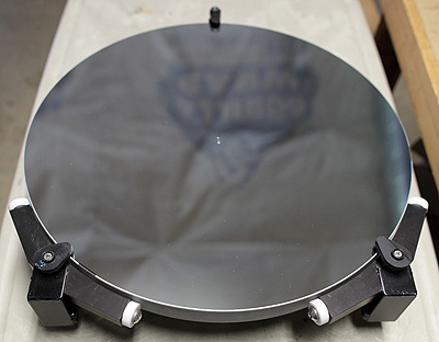
So, this is how John Pratte and I co-discovered the whiffletree and roller edge support, which I believe is the best solution available today, and it has been tested and has worked well for mirrors up through 32" in diameter. We have confirmed that it performs very well on mirrors of a variety of sizes and thicknesses, including very thin mirrors.
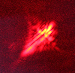
With this edge support and properly made rear supports, there is no collimation shift and stars remain round as the telescope is pointed low in the sky. We have found it to work extremely well for 20" mirrors that are as thin as 1.25" thick, as shown in the photo (at left). Even when pointed low, no astigmatism could be detected for this mirror in the cell when it was tested for figure of revolution in my shop, and also in the telescope.
This is a case where critical observations with a large telescope led to a major improvement in mirror support, which will yield improved images in a wide range of sizes of telescopes. To my knowledge, this is the first time in-lab optical testing has been used to validate and improve amateur mirror edge support systems. In my opinion, based on in-shop and under-the-sky testing, these edge supports produce a small enough amount of distortion that it will be difficult to further improve the edge support, and I do not believe it is necessary in sizes up to and including 32". In short, we have found a solution that we are quite happy with, and we do not believe that any further study of edge support is necessary for mirrors of aperture 32" and smaller.
In addition to JPAstrocraft, StarStructure Telescopes is now also using this type of edge supports. Aurora Precision has also built some cells with this type of edge support. The mirror cells used by Starmaster were the best cells available, in my opinion, until John and I added rollers. It is well known that when you point a Starmaster low, the mirror can hang up on the edge supports when it is raised back up. The solution to this is to point the scope straight up and shake it, or simply nudge the mirror away from the edge supports. The rollers avoid this minor issue.
Update, September 2016: To see how I retrofitted my 20" f/3.0 Starmaster mirror cell with whiffletree and roller edge supports, see this installment of "In the Shop".
Update, May 2020: To summarize and give perspective, I realize that for me, a sling and a tunable-top Paracorr 2 are quite similar - you often have to adjust them through the night and they may not ever be perfectly adjusted. A whiffletree and SIPS are different - you just set them and forget them, they are always perfectly adjusted and give maximum performance, and one spends more time observing and less adjusting.
Update, July 2020: Friction occurs between the rear of the mirror and the rear support points and between the mirror and the edge support. This causes unanticipated things to happen.
Some are quite fond of the two-point edge support, with 90 degrees of separation around the mirror. This arrangement can allow the mirror to get wedged the two points. The mirror settles into the two points, and if they are at all compliant or there is any flexure, the mirror can get "stuck" between them due to the friction between the rollers and the glass. This compresses the mirror. Call it a mirror wedgie.
Many never consider the smoothness/condition of the edge of the mirror, but it can have a profound effect on how well the edge support works because a rougher edge has more friction.
Also, consider what happens as the cell cools off and shrinks - it can cause even more force to be put on the edge of the mirror if it is "stuck" between the two points. Finally, the two-point support puts more force on two small areas of the mirror, resulting in local distortion that is not seen by many of the models, in my experience.
A four-point support, as discussed in the article above, has more rollers, and in my experience this prevents the mirror from getting "stuck" and greatly lowers the local distortion of only two contact points. It's a superb compromise of convenience and performance.
A sling has friction all along the wire where it contacts the glass. As the wire stretches, it sticks to the mirror and can put unpredictable and localized forces on the glass. The larger the mirror, the more unpredictable things become unless precautions are taken. Again, many don't pay attention to how smooth the edge of the mirror is. Also as the temperature changes, if there is significant friction on the back of the mirror, forces can be applied by those contact points in directions perpendicular to the optical axis.
For massive mirrors, the best sling is a roller chain that reduces friction by a couple of orders of magnitude. Stainless steel roller chain will not rust in humid environments.
Rear Support Considerations
Mechanisms/causes other than flexure and edge support issues can contribute significantly to collimation shift. A 42" mirror cell, of the moving-frame design, was constructed with a sling edge support (see photo below, courtesy of John Pratte) and 54 point rear support.
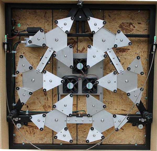 A sling was used because we did not have experience making whiffletrees
for that size mirror, and because it was
easier to implement.
A sling was used because we did not have experience making whiffletrees
for that size mirror, and because it was
easier to implement.Each assembly of flotation triangles has an arm with a pivot in the center. At each end of the arm is a large triangle. Attached to each of the three points of the large triangle is a smaller triangle, and the smaller triangles contact the mirror.
In the image, each rear support assembly supports one third of the mirror with 18 points of support, for a total of 54 points. There is one assembly at the bottom, one at upper left, and one at upper right. The pivot arm for the bottom assembly is oriented horizontally.
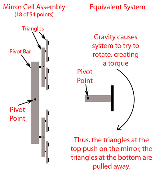
I used this cell for certain testing of a couple of 42" mirrors that I was working on. During my testing, I noticed that when the mirror was nearly on edge, as it would be pointed low in the sky in a telescope, the top of the mirror was actually being pushed away from the supports near the top of the cell. This was undersirable and did not make sense, and clearly was important because it would cause collimation shift and because it the cell is not supporting the mirror properly in this condition. I knew that I needed to figure out what was going on because I would learn a valuable lesson.
 After a little bit of
investigation and thought I found the cause - torque.
After a little bit of
investigation and thought I found the cause - torque.Since the triangles were all stacked on top of each other and were on top of the pivot arms, when the cell was stood up vertically like in the image above, the center of gravity of the triangle/rocker assemblies was forward (toward the primary mirror) of their pivot points. So, the arms want to rotate around the pivot point of the arm, with the triangle group at the top end of the arm (three small triangles, one larger triangle underneath) moving outward, and the triangles at the other end of the arm (also three small, one larger) moving inward. This rotational force is torque.
The illustration at left shows how the mirror cell components are arranged, and shows the equivalent system, which is simply a weight at the end of a bar. This system certainly wants to rotate, because the weight will be pulled down by gravity, and it will rotate around the pivot point, creating a tendency to rotate, or a torque.
Keep in mind that each assembly includes six triangles that contact the mirror and two triangles that support three each of the six triangles, and that is quite a few pounds of aluminum, fasterners, bearings and other parts.
This is a significant amount of mass, and will easily impart unequal forces on the mirror from behind. Because the 18 support points at the top of the mirror are all pushing toward the mirror, they will push the top of the mirror out away from the cell. This will cause a significant and undersirable collimation shift. Additionally, the triangles are no longer uniformly supporting the mirror, so distortion of the mirror's figure will occur when the telescope is pointed at low altitudes.
Referring to the mirror cell photo at the beginning of this section - the bottom assembly of the cell has its pivot arm horizontal, so it is balanced left to right, so the only non-ideal force applied by these triangles is a net rotation about the pivot of the larger triangle. However, since the mass that wants to rotate is less and is on a shorter lever arm, the undesired force applied to the mirror by the bottom assembly is less than that applied by the two upper assemblies. So, the force applied by the top assemblies exert more force than those applied by the bottom assembly, and the net effect is that the top of the mirror is forced to move outward relative to the bottom of the mirror.
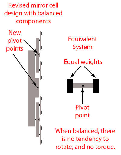 A solution to this problem is to
balance the arm and triangle assemblies so that
equal amounts of mass are on both "sides" of the pivot point of the
arm,
toward the front and rear of the mirror cell, and so that the assembly
balances.
This can be done done by raising the pivot point of the arm closer to
the the
mirror, and also possibly raising the pivot point of the lower triangle
closer to the mirror. The illustration at right shows the
changes made to the cell. To
my knowledge, the only manufacturers who have implemented this or a
variation of it up until
now are JPAstrocraft,
and StarStructure.
A solution to this problem is to
balance the arm and triangle assemblies so that
equal amounts of mass are on both "sides" of the pivot point of the
arm,
toward the front and rear of the mirror cell, and so that the assembly
balances.
This can be done done by raising the pivot point of the arm closer to
the the
mirror, and also possibly raising the pivot point of the lower triangle
closer to the mirror. The illustration at right shows the
changes made to the cell. To
my knowledge, the only manufacturers who have implemented this or a
variation of it up until
now are JPAstrocraft,
and StarStructure.This balancing is important to some extent for all cells, though for heavier, thicker, slower-cooling mirrors it may not make a detectable difference. Balancing is especially important for thin mirrors, because the weight of the support triangles is larger compared to the mirror itself. In these cases, the imbalance will not only cause collimation shift, but the non-uniform force on the triangles can warp the shape of the mirror before the altitude gets low. The thinner the mirror is and the heavier the cell components are, the larger the figure distortion and collimation shift will be.
This discussion should also highlight the idea that the levers, triangles, and support points should all be as thin and low-profile as possible without sacrificing durability during transport when the mirror can literally bounce on top of them. This keeps the total height of the cell to a minimum, keeps the mirror closer to the pivot points, and thus and reduces the torque created by the triangles and levers in cells that are unbalanced.
So, there is a lot going on behind the scenes - and literally behind the mirror - when it comes to the best mirror cell designs in terms of edge support and implementation of the rear support. If you want the highest performance from a thin mirror, you can't cut corners, and you should understand the physics/statics at work in them.
My recommendations are to ask the telescope builder what type of mirror cell they use, and why they use them. If you are buying a telescope from a vendor/builder that is listed on my clients page, chances are they already use the type of cell that I am describing here, but it is not guaranteed at the time of writing of this article. If you are using one of my optics, I will be more than happy to help you find a mirror cell that will support my optics properly at all altitudes.
Secondary mirror support
I do not recommend gluing secondary mirrors to anything unless they are fairly small, or unless you know exactly what you are doing. Certainly do not glue them closely (with a thin glue bond) to metals like steel or aluminum. As the mirror and metal cool, the metal shrinks more than the glass, and this pulls on the mirror and warps its shape. A taller bead of glue that can "roll" and absorb some of the dimensional change will put far less stress on the mirror than a thin layer of glue. Better yet, glue the mirror to a similar material, like another thin piece of Pyrex, then bolt that layer to the secondary holder. Carbon fiber has a lower coefficient of thermal expansion (CTE) than metal, and is more similar to the CTE of glass, and it has been used successfully to attach some optics to.
If you have a truly good secondary mirror, you are starting out ahead, since many have serious flaws. This is why I test and figure each secondary mirror that goes with one of my primary mirrors. Unfortunately I can't easily test them after they're placed in their holders by someone else.
The biggest problem with secondary mirrors is that it is not easy to hold a precision optic firmly - so that it doesn't move and collimation doesn't shift - without bending it. The effect of a "bent" mirror is sometimes obvious, but sometimes subtle. To notice the subtle type of bending, you need good optics, good seeing, good collimation, and maybe some experience in this type of testing. If there are issues in any of those areas, you may not see or be able to recognize the distortion in star shape that the bending usually causes. You have to star test very close to focus to see subtle things, so if you haven't please refer to my article "Why Aren't My Stars Round?".
I tell people to be critical and I encourage and teach them to look for very small things seen close to focus - hints of astigmatism, etc. - that many people miss. In reality these small things are significant, and represent the effect of maybe a quarter wave of mirror bending as a rough estimate. Now, if someone saw a quarter wave of error in a test report for a primary - they might be quite unhappy, or even angry. However, often when I point out the effect of a quarter wave of mirror bending, people are surprised at how subtle the effect is on a normal night. While subtle on an average night, that issue will degrade performance on a superb night, so it should be fixed.
Here we will discuss how to properly put an elliptical, flat, Newtonian secondary mirror into a holder that it hopefully fits properly in. Many people, myself included, have found found that many holders need significant modification to properly hold the secondary mirror without pinching it.
First, for large secondaries (say 4.5" m.a. and larger), it is wise to have a styrofoam "plug" to fill much of the empty space in the holder shell. In the past, this space would have been filled with polyester batting, but the batting is very compressible, so one has to stuff the holder tightly with that batting to keep the secondary in place. Instead, it is better to fill the space with incompressible foam and use less batting, because it will support the mirror more uniformly and in a more stable manner over time. The image below shows how a large secondary holder is assembled.
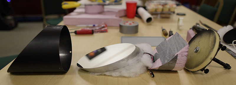
From left to right, we have the shell, mirror, batting, foam plug (held together by duct tape), and the mounting plate/adjustment assembly/stud. There is a dew heater on the back of the secondary mirror.
The shell should be slightly larger in diameter than the secondary mirror, and the lip that keeps the mirror from falling out should contact the mirror as uniformly as possible all the way around the edge of the mirror. Small details are important here - something as simple as making sure the ends of the holder are even, and that the retaining rim is evenly against the mirror as the screws are tightened is very important. Be picky.
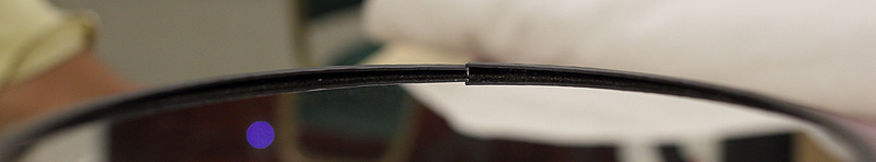
The image above shows a secondary holder shell that has been wrapped around the secondary too tightly. The ends of the holder actually overlapped, as seen in the center of the image. The overlap kept the lip from contacting the mirror uniformly. These problems caused astigmatism that was easily visible in images.
The holder was loosened so that there was a substantial gap at the joint in the shell. This is fine, so long as not too much batting sticks out through the hole. The lip of the holder was also re-bent to contact the mirror all the way around its edge. Though it took several hours of trial and error work to accomplish this and get the holder to fit properly, it greatly improved the images seen through the telescope.
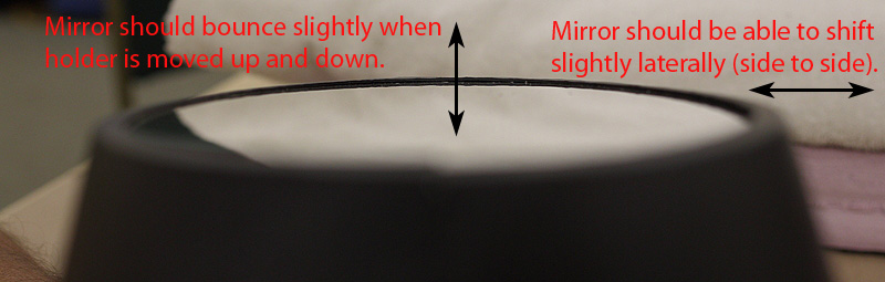
After the mirror is in the holder, I find that the best way to determine if the mirror is in the holder properly is to perform a couple of tests, which I help illustrate with the image above. These tests will tell you if you have too little or too much polyester batting between the secondary mirror and cell, and if it is pinched in the holder.
First, holding the mirror surface parallel to the ground (facing the sky), carefully move the holder up and down somewaht rapidly. The mirror should "bounce" gently within the holder, that is it should move downward slightly away from the lip, and then move back up and make contact with the lip again. You can feel if this is happening as you move the holder up and down - the mirror should not be pushed against the lip so tightly that it is difficult to get it to move downward away from it. With slower movements, it should not move.
Second, moving the holder side to side in any direction should cause the secondary mirror to shift very slightly side to side, and this should be audible as the mirror bumps into the inside of the shell. You should also be able to feel the mirror shifting side to side as you shake it.
If you don't find these two things to be true, take the holder apart and work on it some more. Your persistence will pay off.
If those two conditions are satisfied, and the secondary mirror is against the holder lip all the way around, then chances are secondary mirror will not be bent significantly by the holder. If the holder cannot be made to fit, contact your supplier or put your metal working skills to work.
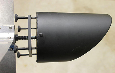
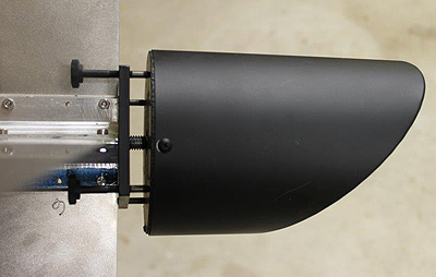
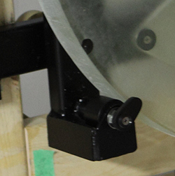
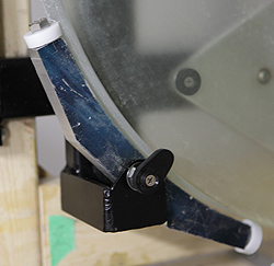
Left, above: Secondary holder too far from spider. Right, above: Secondary holder against spider to reduce flexure.
Some large secondary holders can have a problem with flexure. In these cases, it is best to get the holder as close to the spider as possible. See the photos above (both courtesy of John Pratte). The photo on the left shows a secondary mirror that is far away from the spider, and the threaded rod/stud that attaches it to the spider will flex due to the weight of the secondary and holder. The photo on the right show the holder adjustment plate (plate with the tilt adjustment screws threaded through it) pushed up against the spider, where it cannot flex unless the spider itself is faulty or loose. This is the most rigid arrangement, and is ideal.
Getting the holder that close may mean drilling new holes to mount the spider further downward in the cage, closer to the secondary holder, while the mirror effectively stays in the same spot. I have helped clients do this. I have also helped clients put shims between the spider vanes and the back of the adjustment plate so that the spider itself helps keep the holder from flexing.
Suppliers of holders have made improvements recently so that the shells fit secondary mirrors better, and so that flexure is reduced in larger sizes. Every telescope is different, so you will have to evaluate your telescope independently and see if there is an issue due to flexure.
Conclusion
Supporting mirrors with minimal distortion of the pricise optical figure can be difficult, but we know how to do it.
If you see obvious aberrations in low-power views or inconsistent aberrations, that is a hint that there is a significant problem with mirror support. Small improvements in mirror support can result in large improvements in image quality, or improvements that are only visible on the best of nights. Either is an improvement, and it is worth doing.
I have made many mistakes and it has taken lots of time, thought, testing, and other work to figure out what is going wrong in a mirror cell and how to fix the problems. I am grateful for the help of John Pratte, of JPAstrocraft, whose machining skills have allowed us to experiment with solutions until we found one. There is no doubt that we still have some more to learn for larger mirrors, but we have covered the major points and most common problems in this article.
If you purchase one of my mirrors and put it in your own telescope or one built by one of the builders that I recommend and work with frequently, you will have my support and will get a good primary mirror cell. Membership has its privileges!
I wish you clear skies, good seeing, properly mounted, supported, and collimated optics, and tiny, round stars in your eyepieces.