
Sept. 11, 2016: 20" f/3.0 mirror cell mods and support point experiments
All text and images copyright Michael E. Lockwood, all rights reserved.
When the Starmaster mirror cell was designed about 15 years ago, it had two excellent features - a moving-frame design, and whiffletree edge supports.
The moving-frame design means that everything that touches the mirror moves as collimation is adjusted, including the edge support. In this case, the edge supports are whiffletrees, which contact the mirror at four points along its edge. This means that none of the disadvantages of a sling edge support are present, which has been discussed elsewhere.
 However, the one issue with these
cells is that the edge
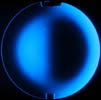
supports often stick to the mirror, and this distorts images slightly
when the telescope is pointed low. The simple solution is to
gently push the mirror away from the edge supports when the distortion
is seen.
However, the one issue with these
cells is that the edge
supports often stick to the mirror, and this distorts images slightly
when the telescope is pointed low. The simple solution is to
gently push the mirror away from the edge supports when the distortion
is seen.Mirror cell design has evolved over the last 15 years, and John Pratte and I came up with an improvement in edge support design - the whiffletree and roller edge support. It is featured in my article A Modern Guide to Mirror Support.
I realized that retrofitting a Starmaster cell is quite simple. All that is required is to machine a piece that rollers attach to and which mounts on the existing whiffletree.
I came up with a design for this while visiting some clients who have a 28" Starmaster, John Pratte made the parts, and I installed them some time ago. They work perfectly. A 30" has also been fitted with these parts. However, I have neglected my 20" f/3.0 MX for too long, and I decided to make my own parts using some 1" thick pieces of Delrin plastic that I have a good supply of.
First, however, I did some experimenting with the mirror cell support points. I determined that the Starmaster cell had a very good idea employed - the cell support points are white Nylon, 1.0" in diameter, and the top surface has a slightly concave shape. This means that the points contact the mirror only at the edge of these pucks, and this actually reduces stiction and friction compared to a flat pad for the material that was used. I did some measurements that confirmed this.
However, the bottom surface is convex, and curves up away from the metal cell triangle. This means they can flex and give a little bit, and is slightly springy under the load of a mirror. I decided that I could make an improvement.
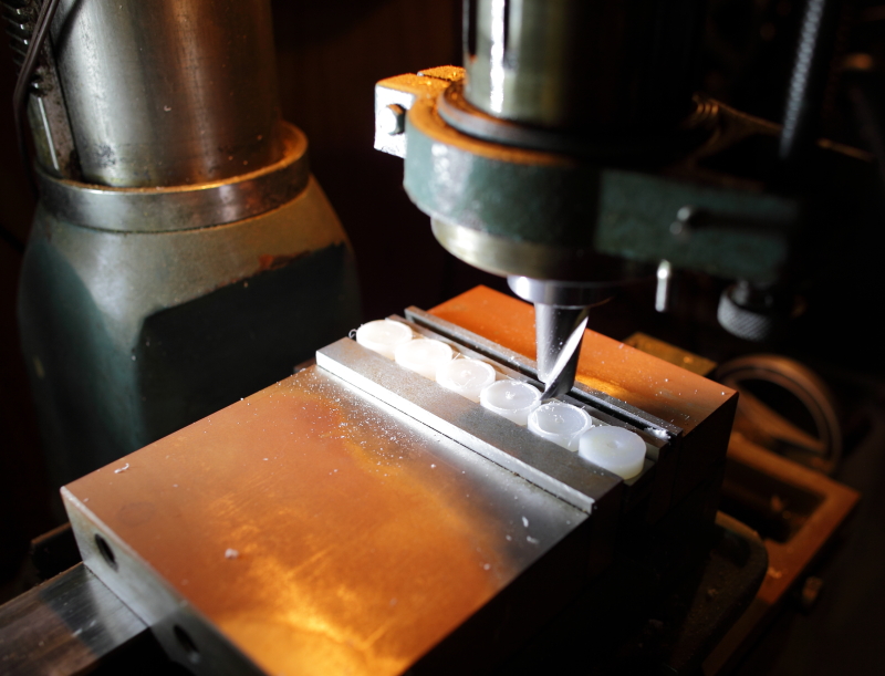
I took all eighteen of the contact points off, and machined a small flat spot on the side of each of them. This allowed me to clamp several of them at a time in the vise on my mill. With a 7/8" diameter end mill I centered each disc by eye and machined away the center of the plastic disc on both sides, removing about 1/32"-3/64" of material from the center 7/8" of the puck. This left a raised rim that was 1/16" wide on the top and bottom of each piece. This is what would then contact the cell triangle on the bottom and the mirror on the top.
Then I reattached each contact point/disc to the triangles, and as they bolts were tightened, they pulled down very securely against the triangle surface thanks to the raised rim. There was no gap between the metal and plastic, and they would not have the opportunity to flex at all.
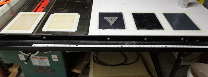
I set up a "sanding array", which consisted of five different grits of sandpaper taped to the table and extension table of my tablesaw, which was a nice flat surface. I had 100, 150, 180, 400, and 600 grit sandpaper available as seen in the image below, left to right. The last three grits were done wet at the recommendation of John Pratte. I sanded all six triangles on each grid, making the surfaces of the contact points on each triangle nicely planar and very smooth.
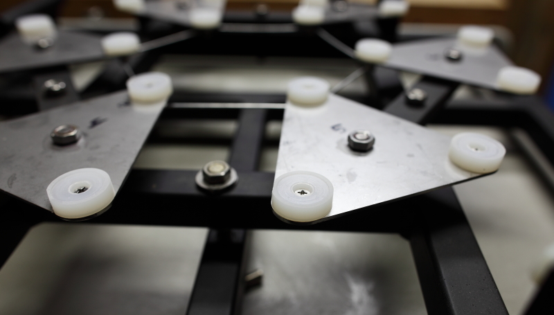
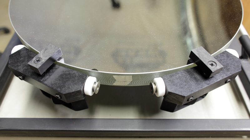
I reinstalled the triangles in the cell, and the mirror sat very securely on all 18 points with absolutely no gap on any contact point that I could see. It moved very easily, and I was quite pleased. Here's a look at the reinstalled pads/discs/contact points.
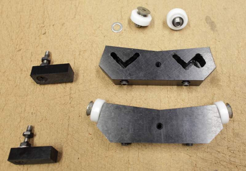
Pleased with this improvement, I began measuring the parts I would need to make to retrofit the whiffletrees with rollers. I cut them to the proper shape, drilled and tapped holes for the bolts to secure the rollers and for bolts to secure the pieces to the old whiffletree. I also drilled new holes to attach the mirror clips to, since the old ones were blocked by the new parts. Finally I carefully marked and machined away pockets in the back side of the rollers to accept the old angle iron that made up the existing whiffletrees. This took some time, but eventually they were made to fit quite nicely.
Here are what the parts look like.
With a little convincing from a rubber hammer, the new parts were made to slip over the old whiffletrees. I marked the center of gravity of the mirror on a piece of tape, rotated the mirror to position the tape at each roller, carefully adjusted the height of each roller, and tightened the bolts that secured them. Because I had been careful, the mirror was still positioned properly in the cell, and I was done with my work. The cell fit back in the telescope with plenty of clearance.
So, if you have some machine tools or simply patience and a drill press, you could make these parts. The 7/8" end mill was the only truly specialty piece of tooling that I used, and I was lucky to have it on hand, otherwise I would have probably used a 3/4" end mill.
An alternative method would have been to mount the original Nylon or Delrin rods on some polished metal shafts that ran through their center. This would have allowed them to slide up and down, and allowed the edge of the mirror to find its proper place. However, mounting the shafts would take time and machining, and there would still be some friction. So, I chose the whiffletree/roller assembly instead.
Now I don't have to push my 1.25"-thick 20" f/3.0 mirror away from the edge supports periodically during my evening's observing, and performance is excellent. Next I'll have to contemplate adding some fans......
The mirror cell contact point work was done as a result of some experiments that John Pratte and I were conducting regarding the friction of various types of contact points. John mocked up six different triangles with different types of contact points, and I included a triangle from the Starmaster cell before I did the machining of the points.
I created an experiment to generate relevant data and help us determine what type of contact point was really the best to use in mirror cells.
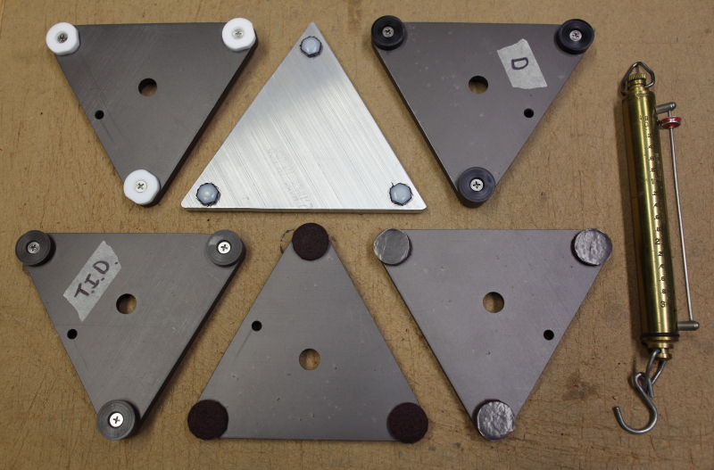
John made the triangles and sanded the contact points down to 400-grit wet sandpaper. All contact points were 1.0" in diameter except for some Nylon bolt heads that were substantially smaller. I borrowed the ground back of a 24" quartz blank that I had on hand to test the stiction of each triangle, and measured this with a small spring scale that I had on hand. The photo below shows the triangles, two of which were modified for a secondary experiment, and the small pull scale that I used to take measurements.
In order from left to right and top to bottom, they are 1) Teflon, 2) Nylon bolt heads, 3) Delrin, 4) Teflon-impregnated Delrin, 5) Felt, and 6) Felt with Teflon film.
The primary experiment was conducted in the following manner.
First, the triangles were all cleaned and rubbed on the back of the mirror for a while to knock off any debris and to burnish them as though a mirror had been slid around or rotated on top of them as it would during normal telescope usage.
Second, the triangle was placed in a particular spot on the back of the mirror, and all other triangles were placed in the same spot. This meant that the condition of the back of the mirror was the same for all triangles, and dirt, oil, etc. were not a factor.
Third, a 4.4 lb weight (2 kg) was placed on the back of the mirror and a timer was set for 20 minutes. Time was found to be a significant factor in the stiction measurements, so a reasonable time was chosen that allowed the experiment to be completed in a reasonable time. When the timer went off, I pulled on the scale with the weight still on the triangle and recorded the amount of force that was required to move the triangle.
This data was quite consistent, and after doing the modifications above to my Starmaster cell I decided to also machine the Delrin and Teflon-impregnated Delrin triangle contact points as I had the Nylon Starmaster cell contact points - by machining away the central 7/8" of material on the top and bottom of points. Then I repeated the measurements above. I also took data for one of the Starmaster cell triangles after machining and sanding.
| Contact
point type |
Pull
force, full contact 400-grit |
Pull
force, machined center, 600 grit |
%
change in force for machined center |
| Teflon |
0.85 kg |
||
| Nylon (bolt
heads, ~1/4" dia.) |
1.14 kg |
||
| Delrin |
0.92 kg |
0.75 kg |
-18% |
| Teflon
impregnated Delrin |
0.84 kg |
0.69 kg |
-18% |
| Felt (new,
clean) |
0.64 kg |
||
| Felt with
teflon adhesive
film |
0.40 kg |
||
| Nylon (1"
dia.)
Starmaster cell |
1.00 kg |
0.68 kg |
-32% |
The conclusions that I can draw based on this data are as follows:
First, despite the relatively low friction of new felt pads and the further reduction using a stick-on piece of teflon film, the felts pads are quite compressible, and this is an unsuitable contact point for a telescope that has tight collimation tolerances. Also, the felt tends to stick to the mirror over time as it accumulates dirt, dust, etc. due to being in an often moist environment. However, for those who are having sticking problems with felt pads and need a quick temporary fix, these adhesive Teflon film pieces may provide a fix that will work fairly well for a while.
Second, it is clear that the machined center and slightly finer sanded pads had lower stiction than the full pads. Since all pads were burnished on the ground back of a mirror, effectively fine-sanding the 400-grit sanded parts, I believe that the main factor in the stiction reduction was the removal of the central contact area.
Third, the reduction of stiction was significant for the three plastics that had the machined centers. This may indicate that less contact area is better, but experiments have not been done to determine if there is an optimum contact area. It is my professional impression that the machined contact points have sufficiently low stiction so that they do not affect the optical performance of the mirror in any significant manner or amount. Also, it is very easy to obtain and machine 1.0" diameter plastic materials, so it is my current opinion that this size is an excellent choice for mirror cell contact points. Small points may work just as well or slightly better, but I have not done that experiment.
Fourth, the removal of the central area of the pad has two other advantages. 1) The triangles take much less time to sand to a plane than the full contact points. This saves time and labor. 2) Removing the central area of the back of the contact pad means that the pad will pull down tightly against the triangle itself, removing any spring action caused by the pad not coming into perfect contact with the triangle. This will slightly improve the telescope's ability to hold collimation, and improves the build quality of the mirror cell.
Please check back for future installments of "In the Shop".
Mike Lockwood
Lockwood Custom Optics